408 Chapter8
IF Section
Troubleshooting Using the TAM
Troubleshooting Using the TAM
When using Automatic Fault Isolation, the TAM indicates suspected
circuits that need to be manually checked. Use Table 8-1 on page 408 to
locate the manual procedure. Table 8-2 on page 410 lists assembly test
connectors associated with each Manual Probe Troubleshooting test.
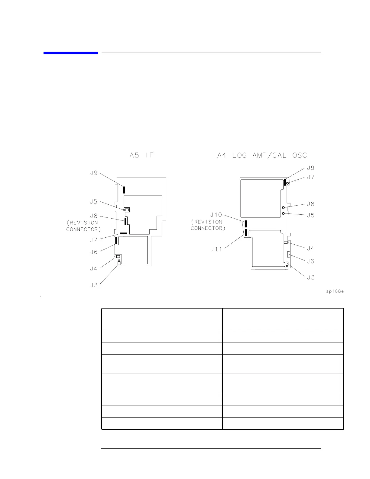
Figure 8-1 on page 408 illustrates the location of A4 and A5 test
connectors. Figure 8-2 on page 412 illustrates the levels and paths
through the IF Section.
Figure 8-1 A4 and A5 Test Connectors
Table 8-1 Automatic Fault Isolation References
Suspected Circuit Indicated by
Automatic Fault Isolation
Manual Procedure to Perform
Check Cal Oscillator on A4 Assembly Troubleshooting the Cal Osc with the TAM
Check Input Switch on A5 IF Assembly Troubleshooting A5 with the TAM
Check Linear Amplifiers on A4
Assembly
Linear Amplifiers
Check Log Expand on A3 Interface
Assembly
Refer to "Log Expand" in this chapter
Check Step Gains on A5 IF Assembly Step Gains
Check Video Offsets on A4 Assembly Video Offset (steps 1 through 4)
Check VIDEO OUT on A4 Assembly Video Output

 Loading...


