Chapter 2 87
Adjustment Procedures
7. YTO Adjustment
7. YTO Adjustment
Assembly Adjusted
A14 frequency control assembly
Related Performance Tests
Frequency Span Accuracy Frequency Readout Accuracy and Frequency
Count Marker Accuracy
Description
The YTO main coil adjustments are made with the phase-lock loops
disabled. The YTO endpoints are adjusted to bring these points within
the capture range of the main loop. The YTO FM coil is adjusted to
place the 300 MHz CAL OUTPUT signal at the center vertical graticule
in a 20 MHz span.
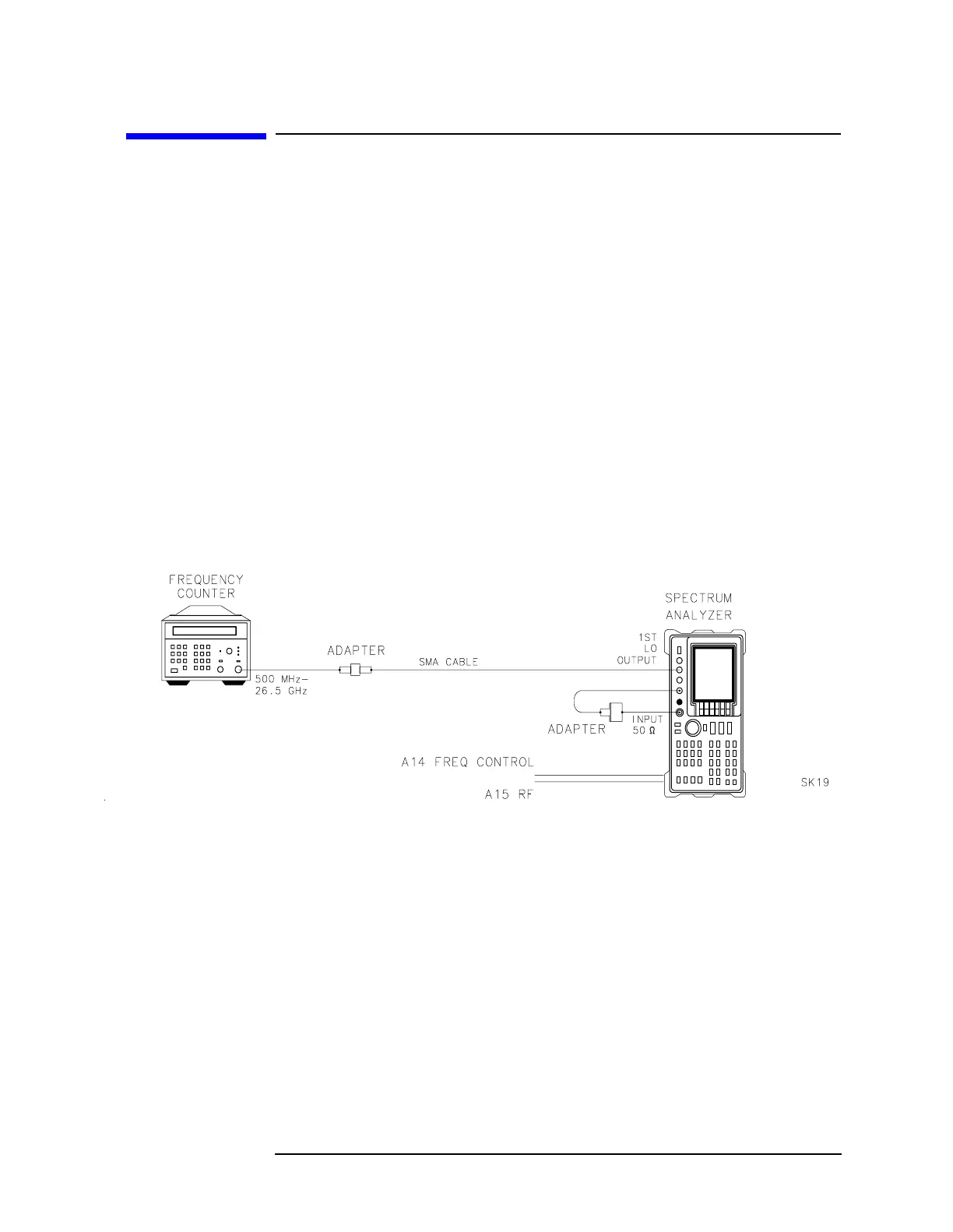
Figure 2-10 YTO Adjustment Setup
Equipment
Microwave frequency counter......................... HP 5343A Option 001
Adapters
Type N (m) to BNC (f) ..............................................1250-1476
Type N (f) to APC 3.5 (f) (Option 026 only).............. 1250-1745
APC 3.5 (f) to APC 3.5 (f)..........................................5061-5311
Cables
BNC, 122 cm (48 in) .......... ..................................... HP10503A
SMA, 61 cm (24 in)....................................................8120-1578

 Loading...


