360 Chapter7
ADC/Interface Section
Keyboard/RPG Problems
Keyboard/RPG Problems
Keyboard Interface
Refer to function block G of A3 Interface Assembly Schematic
Diagram (sheet 3 of 6) in the
HP 8560 E-Series Spectrum Analyzer
Component Level Information.
A pressed key results in a low on a keyboard sense line (LKSNS0
through LKSNS7). This sets the output of NAND gate U607 high,
generating KBD/RPG_IRQ. The CPU determines the key pressed by
setting only one keyboard scan line (LKSCN0 through LKSCN5) low
through U602 and reading the keyboard sense lines.
1. If none of the keys or RPG responds, check ribbon cable, A1A1W1.
(This cable connects the A1A1 keyboard to the A3 interface
assembly.) The keys are arranged in a row/column matrix, as shown
in Table 7-4 on page 360.
2. If an entire row or column of keys does not respond, and the RPG
does respond, there might be an open or shorted wire in A1A1W1.
3. Check that all inputs to NAND gate A3U607 (LKSNS lines) are high
when no key is pressed. If any input is low, continue with the
following:
a. Disconnect A1A1W1 from A3J602 and again check all inputs to
U607.
b. If any input is low with A1A1W1 disconnected, suspect A3U604,
A3U607, or A3U602.
c. Reconnect A1A1W1 to A3J602.
4. Monitor A3U607 pin 8 with a logic probe. A TTL high should be
present when any key is held down. Monitor this point while
pressing each key in succession.
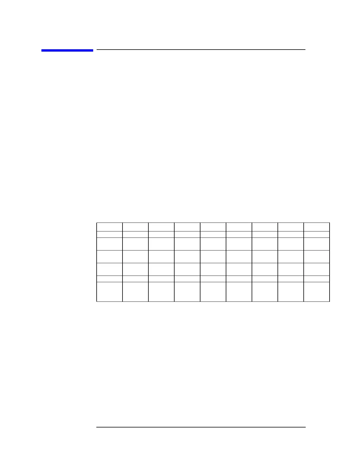
Table 7-4 Keyboard Matrix
LKSNS0 LKSNS1 LKSNS2 LKSNS3 LKSNS4 LKSNS5 LKSNS6 LKSNS7
LKSCN0 CONFIG SAVE RECALL GHz MHz kHz Hz PRESET
LKSCN1 MODULE TRIG DISP 9 6 3 BK SP ↑
LKSCN2 PEAK BW TRACE 852•↓
SEARCH
LKSCN3 FREQ AUTO MKR → 7410HOLD
COUNT COUPLE
LKSCN4 SWEEP SK1 SK2 SK3 SK4 SK5 SK6 MKR
LKSCN5 AUX MEAS/
USER
CAL SGL COPY FRE- SPAN AMPLI-
CTRL SWP QUENCY TUDE

 Loading...


