Chapter 2 61
Adjustment Procedures
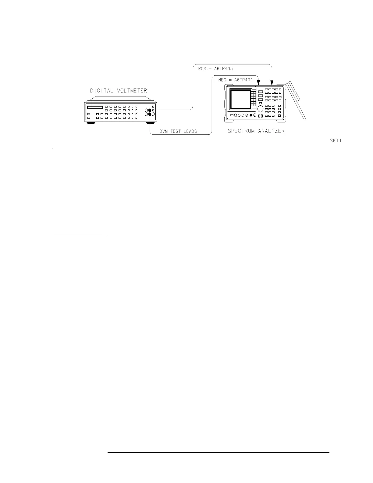
1. High Voltage Power Supply Adjustment (8560E only)
Figure 2-1 High Voltage Power Supply Adjustment Setup
Equipment
Digital multimeter ...............................HP 3456A
DVM test leads ................................... HP 34118A
Procedure
WARNING After disconnecting the ac power cord, allow capacitors in the
high voltage supply to discharge for at least 30 seconds before
removing the protective cover from the A6 power supply.
1. Press
LINE to turn the spectrum analyzer off, disconnect the power
cord, and remove the spectrum analyzer cover. Fold down the A2
controller, A3 interface, A4 log amplifier, and A5 IF assemblies.
Remove the A6 power supply cover.
2. Position the HP 8560E/EC as shown in Figure 2-1. Connect the
negative DVM lead to A6TP401 and the positive DVM lead to
A6TP405 (place the positive DVM lead on the inductor (L401) lead
which is adjacent to the label that reads “U401”; a white square
outlines the area on the PC board where this lead is inserted into the
A6 board).
3. Set the HP 3456A controls as follows:
Function ......................................... DC VOLTS
Range ............................................. 1000 VOLTS
4. Reconnect the power cord to the spectrum analyzer and press
LINE to
turn the spectrum analyzer on.
5. Record the voltage marked on the A6A1 HV module.

 Loading...


