3: Functions and features Model 2450 Interactive SourceMeter® Instrument
3-62 2450-901-01 Rev. B/September 2013
Digital I/O
You can use the Model 2450 digital input/output with the trigger model or to control an external digital
circuit, such as a device handler that is used to perform binning operations. To control or configure
any of the six digital input/output lines, send commands to the Model 2450 over a remote interface.
To use the Model 2450 digital I/O in a trigger link system (TLINK), connect it using a Model
2450-TLINK Trigger Link Cable and configure the Model 2450 digital input and output lines.
For more information the trigger model, see Trigger model (on page 3-95
).
Digital I/O port
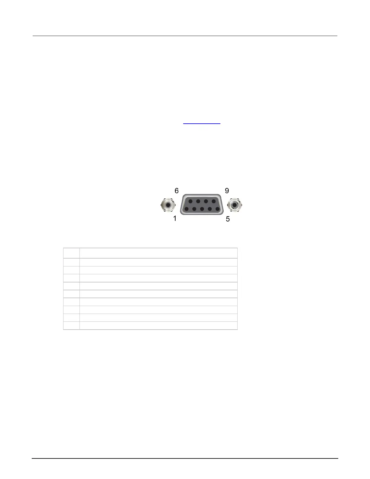
The digital I/O port uses a standard female DB-9 connector, which is located on the rear panel of the
Model 2450. You can connect to the Model 2450 digital I/O using a standard male DB-9 connector.
The port provides a connection point to each of the six digital I/O lines and other connections as
shown in the following table.
Figure 91: Model 2450 digital IO port
Model 2450 digital I/O port pinouts
Pin Description
Vext line (relay flyback diode protection)
* Use this pin to drive external logic circuitry. Maximum current output
is 500 mA. This line is protected by a self-resetting fuse (one-hour

 Loading...


