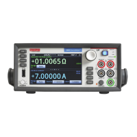
3: Functions and features Model 2450 Interactive SourceMeter® Instrument
3-70 2450-901-01 Rev. B/September 2013
Set up a limit test using the remote interface
You can set up limit testing through a remote interface. There are several methods you can use to set
up the limit test:
• Scripting (available with TSP only): Allows the most flexibility; you can set up the limit test as
needed.
• Trigger model: Provides the best speed and throughput, using pre-defined trigger blocks to
simplify set up.
The following topics show examples using simple and complex limit and binning tests.
Resistor grading using limit testing
This limit test inspects multiple limits until the first failure is received. When a resistor fails, it is sorted
into the appropriate bin.
This example grades resistors into tolerance levels (for example, 20%, 10%, 5% and 1%). A single
spot measurement is inspected against multiple limits, which tighten progressively around the same
nominal value. Since there is no reason to continue limit checking once the appropriate tolerance
level for a resistor-under-test is determined, this application will typically immediately bin the tested
resistors. The bit patterns assigned to the limits determine into which bin a resistor is placed.
For this example, the same fail bit pattern is assigned to both the lower and upper bounds of the limits
so that resistors with resistance values in the range R-P% to R go into the same bin as those with
resistance values in the range R to R+P%. If you want to put parts in separate bins that correspond to
R-P% to R and R to R+P%, you can do so by assigning different bit patterns for the upper and lower
bounds of the limits.
Since the limits are inspected in ascending numeric order, the measured resistance is checked first
against Limit 2, which is the 20% limit. If a resistor fails this limit inspection, its resistance value is
outside of the 20% tolerance band and it is considered to be a bad part. The trigger model outputs the
Limit 2 fail bit pattern, which causes the component handler to place the resistor in the Bad Part bin.
If a resistor passes the 20% limit test, the resistance value is checked against the 10% limit value. If
the resistor fails this limit inspection, the resistance is outside of the 10% tolerance band, but in the
20% band. The trigger model outputs the Limit 3 fail bit pattern, which causes the component handler
to place the resistor in the 20% tolerance part bin.
If a resistor passes the 10% limit test, the resistance value is checked against the 5% limit value, and
so on. If a resistor passes all the limit tests, the trigger model outputs the overall pass bit pattern,
which causes the component handler to place the resistor in the 1% tolerance part bin.
 Loading...

