76
2.6 Optical Unit
REGIUS MODEL 190 Service Manual Ver.1.00 2004.11.01
2.6.2 Replacement of Optical Unit
Caution The optical unit is made up of precision compo-
nents: Be sure to avoid banging or knocking
these components during installation or removal.
Caution Laser diode may be damaged due to the electro-
static generated by human body. Always wear a
wrist strap to avoid the electrostatic.
1.
Open the front cover.
2.
Remove the right and left covers. ("2.2.2 Removal of the
Left & Right Covers, p.29")
3.
Remove the front-top cover. ("2.2.3 Removal of the Front-
Top Cover, p.30")
4.
Remove the insertion / ejection unit. ("2.3.2 Removal of the
Insertion/Ejection Unit, p.37")
5.
Remove the photomultiplier. ("2.6.1 Replacement of
Photomultiplier (PMT), p.75")
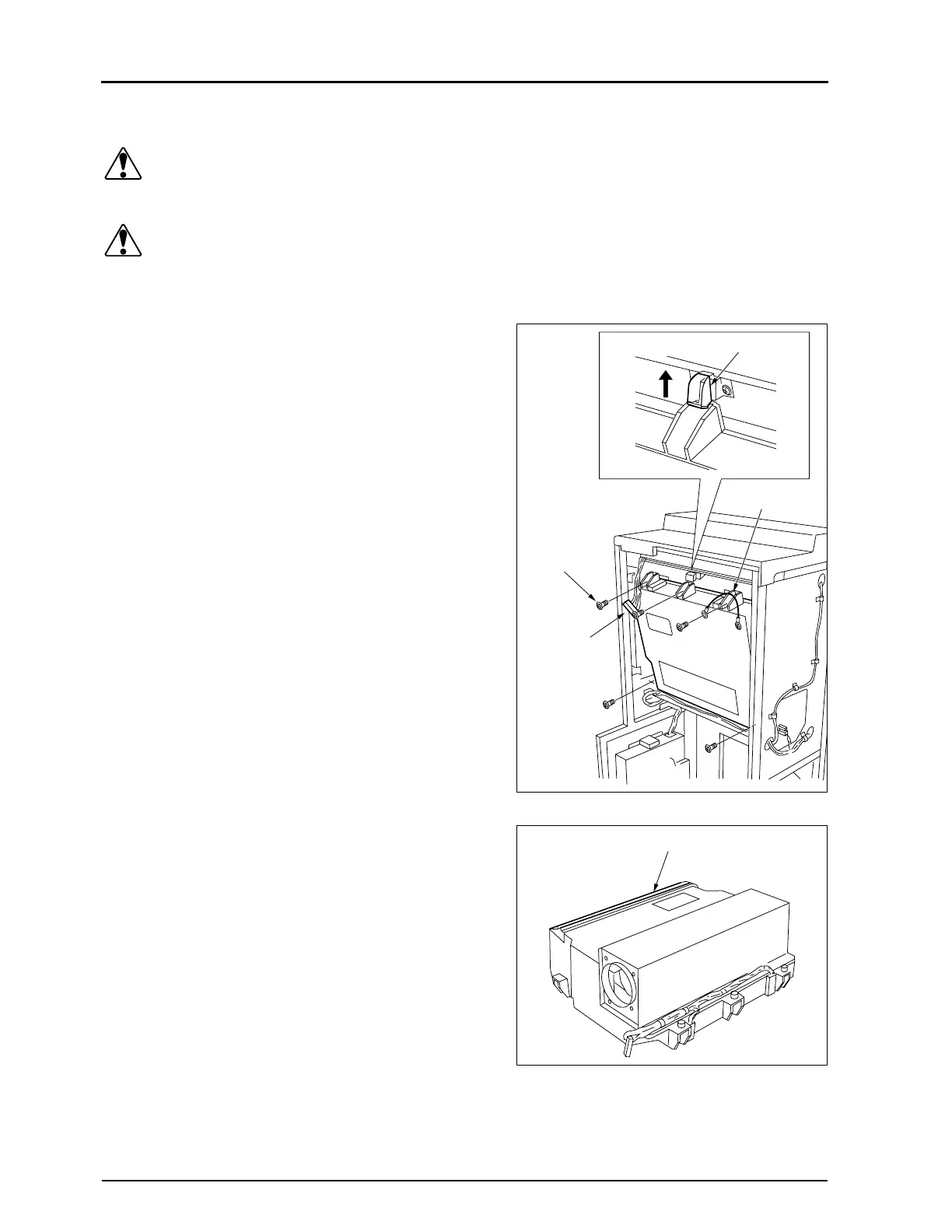
6.
Unplug a relay connector.
• JJ37
7.
Remove 5 fixing screws.
• The fixing screw on the upper right also fixes the earth
cable of the optical unit to the frame.
8.
Hold the optical unit to prevent it from toppling over and lift
up the stopper.
9.
Raise the optical unit by several millimeters and remove it
from the main unit.
• Raising the optical unit allows the protrusions on its
lower side to move clear of the main unit.
10.
Place the cut filter (blue) for excitation light with its face up,
and put a cover (plastic sheet, etc.) so that dust will not stick
to the filter surface.
11.
Carry out reassembly in the reverse order to that described
above.
• Make sure that the earth cable of the optical unit is fixed
to the frame with the fixing screw.
Fixing Screws
(5pcs)
Relay
Connector
Earth Cable
Stopper
Cut Filter for Exitation Light
 Loading...