Home
Konica Minolta
Medical Equipment
REGIUS 190
Konica Minolta REGIUS 190 Service Manual
4
of 1
of 1 rating
220 pages
Give review
Manual
Specs
To Next Page
To Next Page
To Previous Page
To Previous Page
Loading...
28
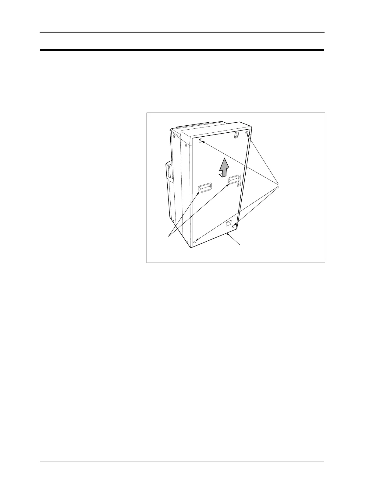
2.2 Removing the External Covers
REGIUS MODEL 190 Service Manual Ver.1.00 2004.11.01
2.2
Remo
ving the External Covers
2.2.1
Remov
al of the Rear Cover
1.
Unscrew and remo
ve the f
our
fi
xing screws (4pcs).
2.
Grip the handle and lift up the rear cover to remo
ve it.
Fixing Screws
(4pcs)
Rear Cover
Handle
54
56
Table of Contents
Table of Contents
2
Principal Specifications
30
Reading the Image
30
Control Unit
33
Specifications
34
Name of Parts
35
External View of REGIUS 190
35
Main Parts Inside REGIUS 190
37
Name of Cassette Parts
38
Layout of Controlling Components
40
Layout of Power Supplies and Main Boards
40
Locations of Motors and Fans
41
Locations of Sensors and Switches
42
Block Diagram
44
Description of Operation
46
Operation Flow
46
Normal Operation
47
Initializing Sequence
50
Erase Operation
50
Required Tools
51
Chap.2 Disassembly and Reassembly
52
Preparation for Disassembly
54
Precautions for Disassembly and Reassembly
54
Removing the External Covers
55
Removal of the Rear Cover
55
Removal of the Left & Right Covers
56
Removal of the Front-Top Cover
57
Removal of Insertion / Ejection Front Cover
58
Removal of LCD
59
Insertion / Ejection Unit
60
Controlling Parts of Insertion / Ejection Unit
60
Removal of the Insertion/Ejection Unit
64
Removal of Ejection Guide Assy
66
Replacement of Bar Code Reader
67
Replacement of Insertion Nip Rollers
68
Replacement of Insertion Motor
70
Replacement of Shutter Motor (M2)
71
Replacement of Ejection Motor (M3)
72
Transport Unit
76
Controlling Parts Comprising the Transport Unit
76
Removal of the Cassette Receive Unit
81
Replacement of the Justification Motor (PM2)
82
Replacement of Transport Rack Gear
84
Replacement of Elevator Motor (PM1)
86
Replacement of Transport Motor (PM3)
87
Unlock Motor (M4)
88
Replacement of Receiver Sensor
90
Subscan Unit
91
Controlling Parts of Subscan Unit
91
Replacement of Cassette Magnetizing Plate
93
Steel Belt Decelerating Unit
95
Replacement of Peel Detect Sensor 1/2 (S13 /S14)
97
Removal of the Sensor Assembly
98
Replacement of Subscanning Motor (PM4)
100
Optical Unit
102
Replacement of Photomultiplier (PMT)
102
Replacement of Optical Unit
103
Replacement of Erasing Lamps
105
Replacement of Thermostat (TH1)
106
Checking H-Sync Signal
107
Electrical Unit
108
Replacement of MCB2 (System Control Board)
108
Replacement of CF Card
110
Replacement of SCB2 (System Control Board)
111
Replacement of ADB2 (A/D Board)
113
Replacement of PSB (±15V Supply)
114
Replacement of SUP1 (DC5V / 24V Supply)
115
Replacement of SUP3(Halogen Power Supply)
116
Replacement of TAP (Power Supply Voltage Switching Board)
117
Maintenance Items
120
Maintenance & Service Schedule
120
Lubrication of the LM Guide
121
Lubrication to the Transport Motor Gears
122
Lubrication to the Release Shaft Holder
123
Cleaning of Power Supply Fan Filter
124
Cleaning of Cassette Magnetizing Plate
125
Set up of Dummy SBC2 Program
126
Installing the Dummy SBC2 Program
126
Connection
127
Start up of REGIUS 190
128
Starting the Dummy SBC2 Program
129
Cautions in Operation of Dummy SCB2 Software
131
Verification of Initializing Sequence
132
Verification of Reading Operation
135
Checking the Stand-Alone Operation
143
Adjusting the Peel-Detection Rollers
144
Peel Detection Mechanism
144
Adjustment of the Standard Position
147
Adjustment of the Sensor Detect Position
148
Adjusting the Pressing Amount
149
Checking and Adjusting the Justification Allowance
151
Adjusting the Position of Insertion Guide Switch (SW4)
152
Troubleshooting for Electrical Control & Communication
156
Network Problems
156
Power Supply On/Off Problems
159
Signal Processing Problems
161
Troubleshooting for Mechanical Troubles
162
Caution for Receiver Sensor Plunger
162
Troubles When Separating / Coupling the Mammo Cassette
163
Actions When a Foreign Material Falls in to the Insertion Slot
164
Troubleshooting for Image Quality
165
Flow of Troubleshooting
165
Case 1: Entire Image Is too Dark (with Subject Structure)
165
Case 2: Entire Image Is too Bright, Whitish (with Subject Structure)
166
Case 3: Horizontal Streaks in Image
167
Case 4: Horizontal Lines Throughout the Entire Image
168
Case 5: Vertical Lines
169
Case 6: False Contours Can be Seen in the Image
171
Case 7: Jittering Can be Seen (I.e., Zigzags in Vertical Lines)
171
Case 8: Image Dimensions Are Incorrect (Vertical Direction)
171
Case 9: Image Dimensions Are Incorrect (Horizontal Direction)
171
Case 10: the Top and Bottom of the Image Are Disconnected
171
Case 11: the Left and Right of the Image Are Disconnected
172
Case 12: Irregularity Correction Has Not Been Carried out
172
Case 13: the Irregularity Correction Data Is Excessive
172
(I.e., 300 Steps or more from MAX to MIN)
172
Case 14: S-Value Variation
173
Case 15: Poor Contrast (Raw Data)
173
Case 16: Density Differs from the Left to the Right
173
Case 17: Dose Irregularities (I.e., Bad Correspondence of Mas and S Values, Etc.)
174
Case 18: Image Disparity
174
Case 19: White Blotches
174
Case 20: Black Blotches
174
Case 21: Monitor Display Problems (OK with Film)
174
Case 22: Image Duplication
175
Case 23: Sensitivity Correction Is Not Within the Specified Range
175
Case 24: All Post-Processing Images Have High Contrast
175
Case 25: All Post-Processing Images Have Low Contrast
175
Case 26: Image Fading
176
Error Code
177
General Procedures Required When Error Occurs
177
Mechanical Control Error Codes
178
Mechanical Control Error Code (04101 ~ 04106)
182
Mechanical Control Error Code (04150 ~ 04165)
183
Mechanical Control Error Code (04200 ~ 04219)
185
Mechanical Control Error Code (04900 ~ 04908)
188
SCB2 Error Codes
190
Network Errors
193
SCB2 Dummy Program Screens
196
Main Window
196
Information" Window
198
Communication Port" Dialogue
199
SCB2 Properties" Dialogue
200
SCB2 Properties" Dialogue
201
SCB2 Error Transmission" Dialogue
202
Maintenance Window
203
Get Task Information" Dialogue
209
Change Data" Dialogue
209
Firmware Update Parameters" Dialogue
210
DIP Switch Setting
211
DIP Switches on the MCB2 (System Control Board)
211
DIP Switches on the ADB2 (Analogue/Digital Board)
213
Replacement Procedures of CF Card
214
Main Circuit Diagram
216
Parts Layout Diagram
217
MCB2 (System Control Board)
217
SCB2 (System Control Board)
218
ADB2 (A/D Board)
219
Other manuals for Konica Minolta REGIUS 190
Operation Manual
68 pages
4
Based on 1 rating
Ask a question
Give review
Questions and Answers:
Need help?
Do you have a question about the Konica Minolta REGIUS 190 and is the answer not in the manual?
Ask a question
Konica Minolta REGIUS 190 Specifications
General
Brand
Konica Minolta
Model
REGIUS 190
Category
Medical Equipment
Language
English
Related product manuals
Konica Minolta AeroDR System
140 pages
Konica Minolta CS-3
200 pages
Konica Minolta DRYPRO 873
124 pages
Konica Minolta Ultra KDR
9 pages
Konica Minolta KDR AU DDR
146 pages
Konica Minolta mKDR Xpress
186 pages
Konica Minolta AeroDR System 2
140 pages
 Loading...