33
2.3 Insertion / Ejection Unit
REGIUS MODEL 190 Service Manual Ver.1.00 2004.11.01
2.3 Insertion / Ejection Unit
2.3.1 Controlling Parts of Insertion / Ejection Unit
•
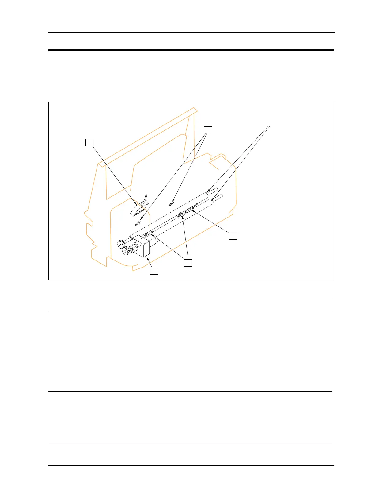
Controlling parts in the area of insertion nip rollers
Insertion Nip Rollers
1
3
4
2
5
Part Name Function Access to the Part
1 Insertion Slot sen-
sor Receiver Side
(LPB1, LPB2)
Detects the inserted
cassette.
1) Remove the ejection guide assy.
•Refer to "2.3.3 Removal of Ejection Guide Assy, p.39"
2) Remove the cassette stacker.
•Refer to"2.3.4 Replacement of Bar Code Reader, p.40".
3) Remove the stay.
•Refer to "2.3.4 Replacement of Bar Code Reader, p.40".
4) Remove the fixing screws (one for each sensor).
5) Unplug the connector (one for each sensor)
•Left: JP57, Center: JP55
2 Insertion Slot Sensor
Emission Side
(LLB1, LLB2)
Emits light against 1. 1) Remove the insertion / ejection unit front cover.
•Refer to "2.2.4 Removal of Insertion / Ejection Front Cover,
p.31".
2) Remove the fixing screws (one for each sensor).
3) Unplug the connector (one for each sensor)
•Left: JP58, Center: JP56
3 Bar Code Reader
Reads the bar code
label
Refer to "2.3.4 Replacement of Bar Code Reader, p.40".
 Loading...