86
2.7 Electrical Unit
REGIUS MODEL 190 Service Manual Ver.1.00 2004.11.01
2.7.4 Replacement of ADB2 (A/D board)
1.
Remove the left cover. ("2.2.2 Removal of the Left & Right
Covers, p.29")
2.
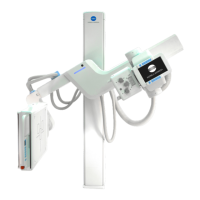
Loosen 6 fixing screws. Then detach the board cover.
3.
Wear an earth strap.
4.
Pull out the SCB2.
5.
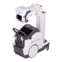
Unplug 8 connectors from ADB2.
• CN2
CN3, CN4, CN5, CN7, CN8, J1, J3
6.
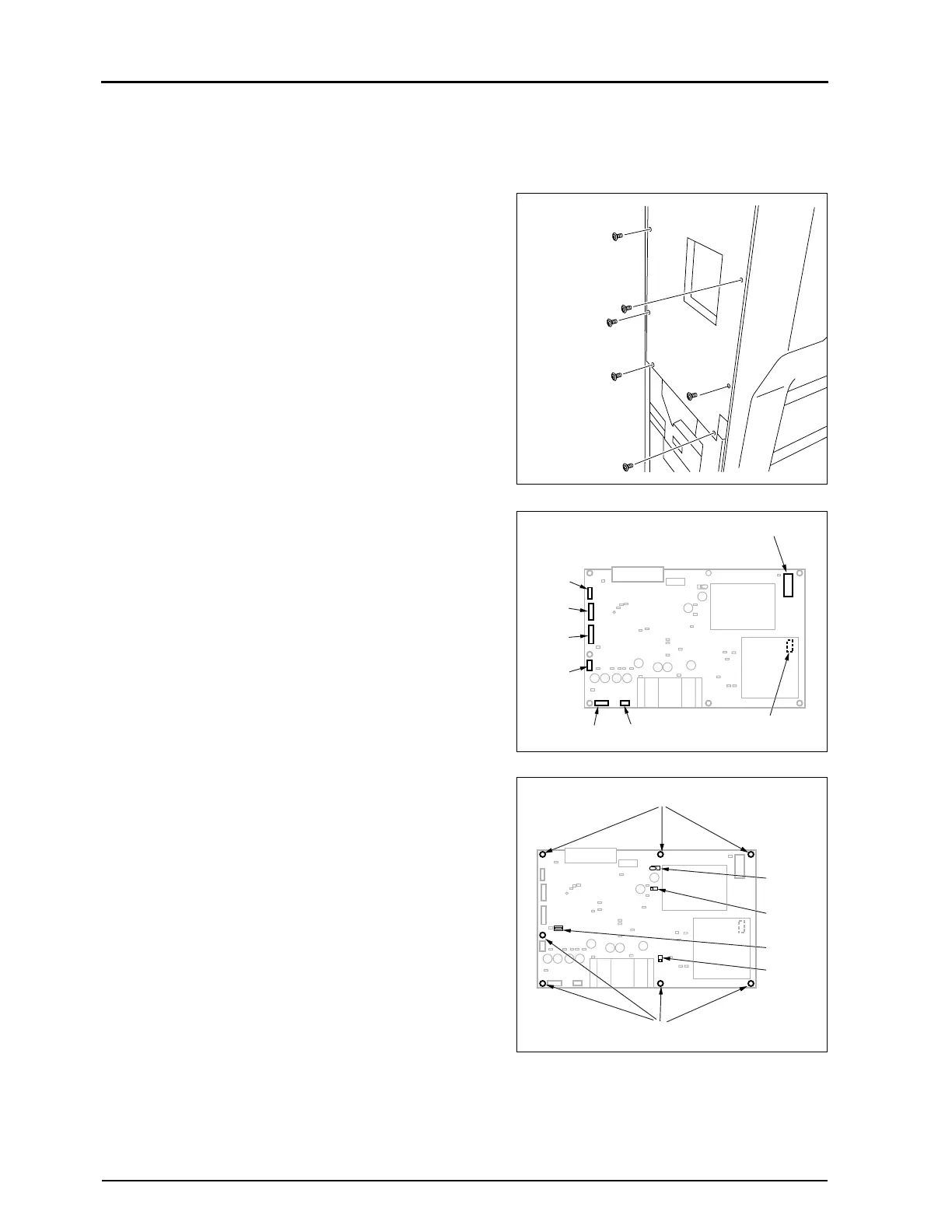
Remove 5 fixing screws, and pull out ADB2.
7.
Carry out reassembly in the reverse order to that described
above.
• Remarks for installation
•Check that the HVSW is set to ON (left).
•Check that all dips of SW1 are set to ON.
•Check that the SW2 and SW4 (auto / manual switching) are
set to "Auto".
Fixing Screw 6pcs)
(loosen)
ADB2
J1
J3
CN3 CN7
CN5
CN4
CN2
CN8
ADB2
SW2
SW1
SW4
HVSW
Fixing Screws
Fixing Screws
 Loading...