EasyManuals Logo

Konica Minolta REGIUS 190 Service Manual

Konica Minolta REGIUS 190
220 pages
To Next Page IconTo Next Page
To Previous Page IconTo Previous Page
Page #40 background imageLoading...
Page #40 background image
13
1.3 Layout of Controlling Components
REGIUS MODEL 190 Service Manual Ver.1.00 2004.11.01
1.3 Layout of Controlling Components
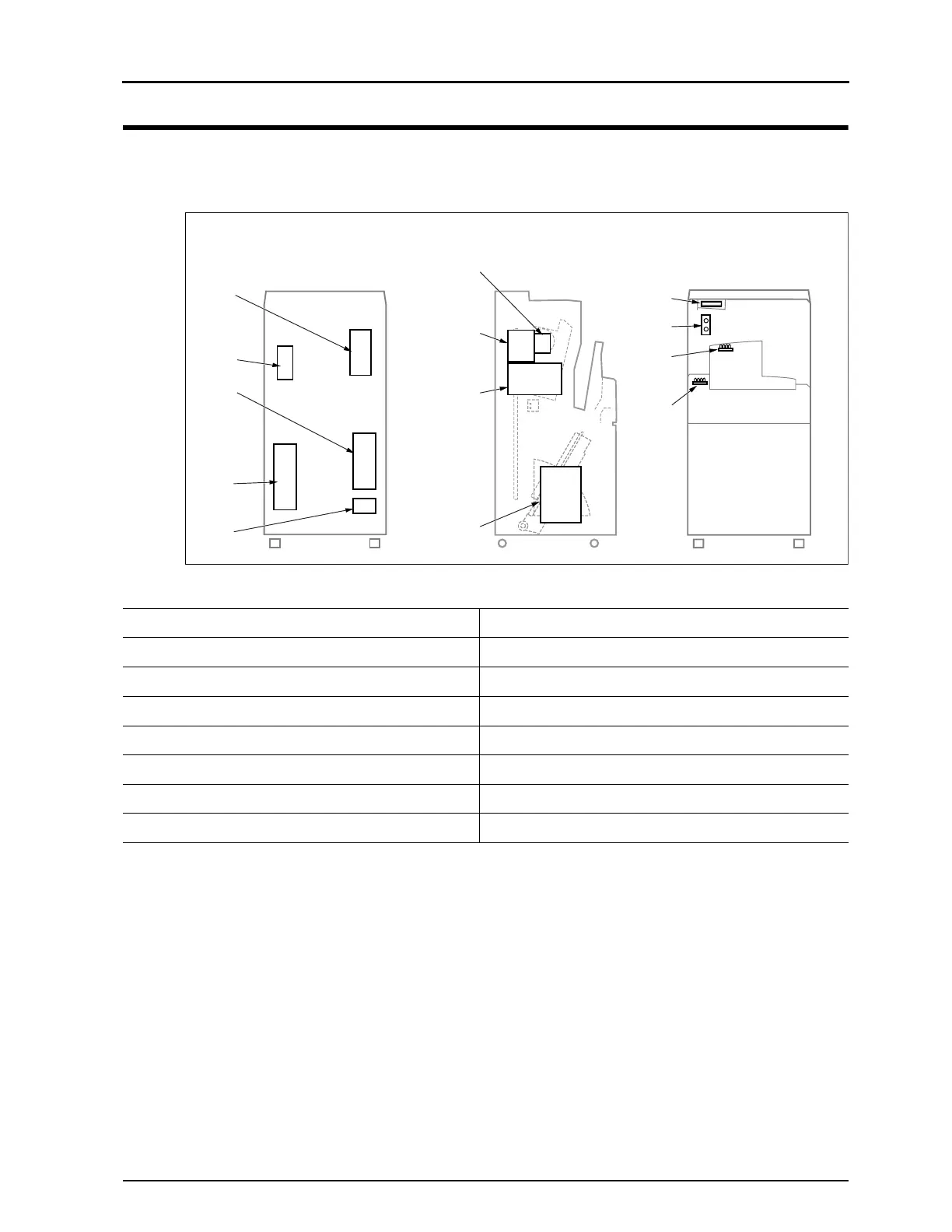
1.3.1 Layout of Power Supplies and Main Boards
No. Part Name No. Part Name
1
SUP1 (DC5V/24V power supply)
8
ADB2 (A/D board)
2
PSB (±15V power supply)
9
MCB2 (Mechanical control board)
3
Power Transformer (PT1) 10 LCD Panel
4 SUP3 (Halogen power supply) 11 GYB (Green Yellow LED board)
5 TAP (Power Voltage Switching Board) 12 ELB (Cassette ejection lamp)
6 Photomultiplier (Breeder circuit) 13 BLB (READY lamp)
7 SCB2 (System control board)
4
5
6
7
8
9
10
11
12
13
1
2
3
Rear
Left
Front

Table of Contents

Other manuals for Konica Minolta REGIUS 190

Questions and Answers:

Question and Answer IconNeed help?

Do you have a question about the Konica Minolta REGIUS 190 and is the answer not in the manual?

Konica Minolta REGIUS 190 Specifications

General IconGeneral
BrandKonica Minolta
ModelREGIUS 190
CategoryMedical Equipment
LanguageEnglish

Related product manuals