Scanner Unit
SM 4-39 D037/D038/D040/D041
Replacement
& Adjustment
10. Screw the drive pulley to the shaft [G].
11. Screw the scanner wire bracket to the front rail [H].
12. Install the scanner wire clamp [I].
13. Pull out the positioning pins.
Make sure the 1st and 2nd carriages move smoothly after you remove the
positioning pins. Do steps 8 through 13 again if they do not.
4.5.10 REAR SCANNER WIRE
1. Rear Cover ( Section: Rear Cover)
2. Operation panel ( Section:.Operation Panel)
3. Exposure glass ( Section: Exposure Glass)
4. Scanner left cover ( Section: Front Scanner Wire)
5. Scanner front frame ( Section: Front Scanner Wire)
6. Scanner left stay ( Section: Front Scanner Wire)
7. Scanner rear frame ( Section: Front Scanner Wire)
8. Follow steps 10 through 14 in Section: Front Scanner Wire. You can remove the rear
scanner wire with the same manner for replacing the front scanner wire.
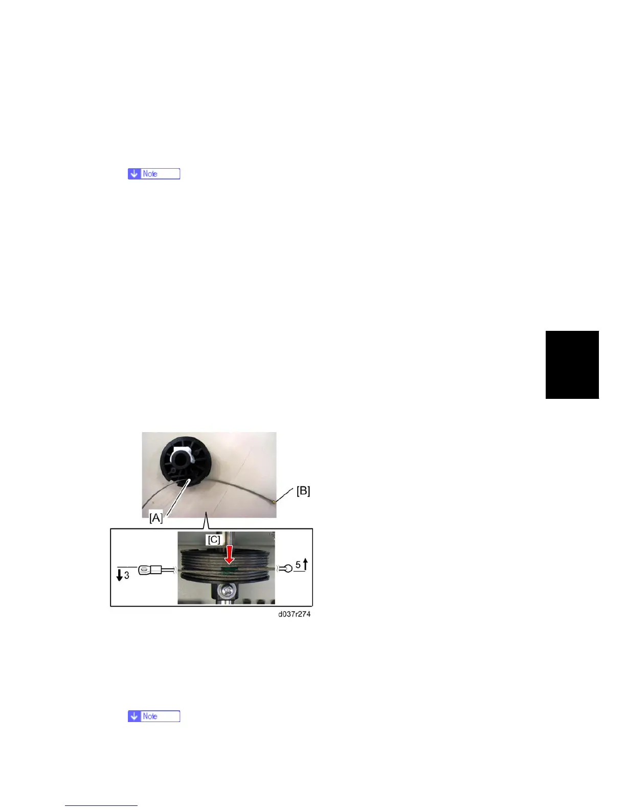
Reinstalling the Rear Scanner Wire
1. Position the center ball [A] in the middle of the forked holder.
2. Pass the left end (with the ball) [B] through the drive pulley notch. Pass the right end
(with the ring) through the drive pulley hole.
3. Wind the left end [B] clockwise (shown from the machine’s front) five times. Wind the
right end counterclockwise three times.
 Loading...