1) Remove cylinder head cover.
2) Remove ignition
timing check window
rubber plug from clutch housing of trans-
mission case.
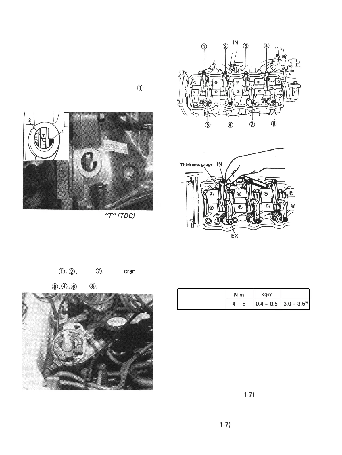
3)Turn crankshaft clockwise (viewing from
crankshaft pulley side) to the extent that
line @above “T” mark punched on fly-
wheel is aligned with match mark
@
on
transmission case as shown below, i.e. No. 1
cylinder piston reaches TDC position.
Fig. 3-8-2 1. Match mark 2.
‘7”
(TDC) mark
4) Remove distributor cap and check that rotor
is positioned as shown in figure. If rotor is
out of place, turn crankshaft clockwise
once (360”). In this state, check valve lashes
at valves
@,@I,
@and
0.
Rotate
cran
kshaft
exactly one turn, and check the same at
valves
8,
@,
@
and
@I.
Fig. 3-8-3
EX
Fig. 3-8-4
-
Fig. 3-8-5 Measuring valve lashes
5) Upon completion of check and adjustment,
install cylinder head cover and torque bolts
to specification.
Tightening torque
N.,.,.,
for cylinder head
I
b-m
lb-ft
cover bolts
4-5
0.4
-
0.5
3.0
-
3.5*
6) Install distributor cap and connect blow-by
gas hose to cylinder head cover.
Camshaft Timing Belt
For checking procedures of damage, wear and
tension of camshaft timing belt, refer to SEC-
TION 1 (p. 1-5) of this manual.
Engine Oil
Refer to SECTION 1 (p.
I-7)
of this manual.
Engine Oil Filter
For removal and installation of filter, refer to
SECTION 1 (p.
I-7)
of this manual.
3-54
 Loading...


