5) Install gaskets and drain plugs, after installing
main jets.
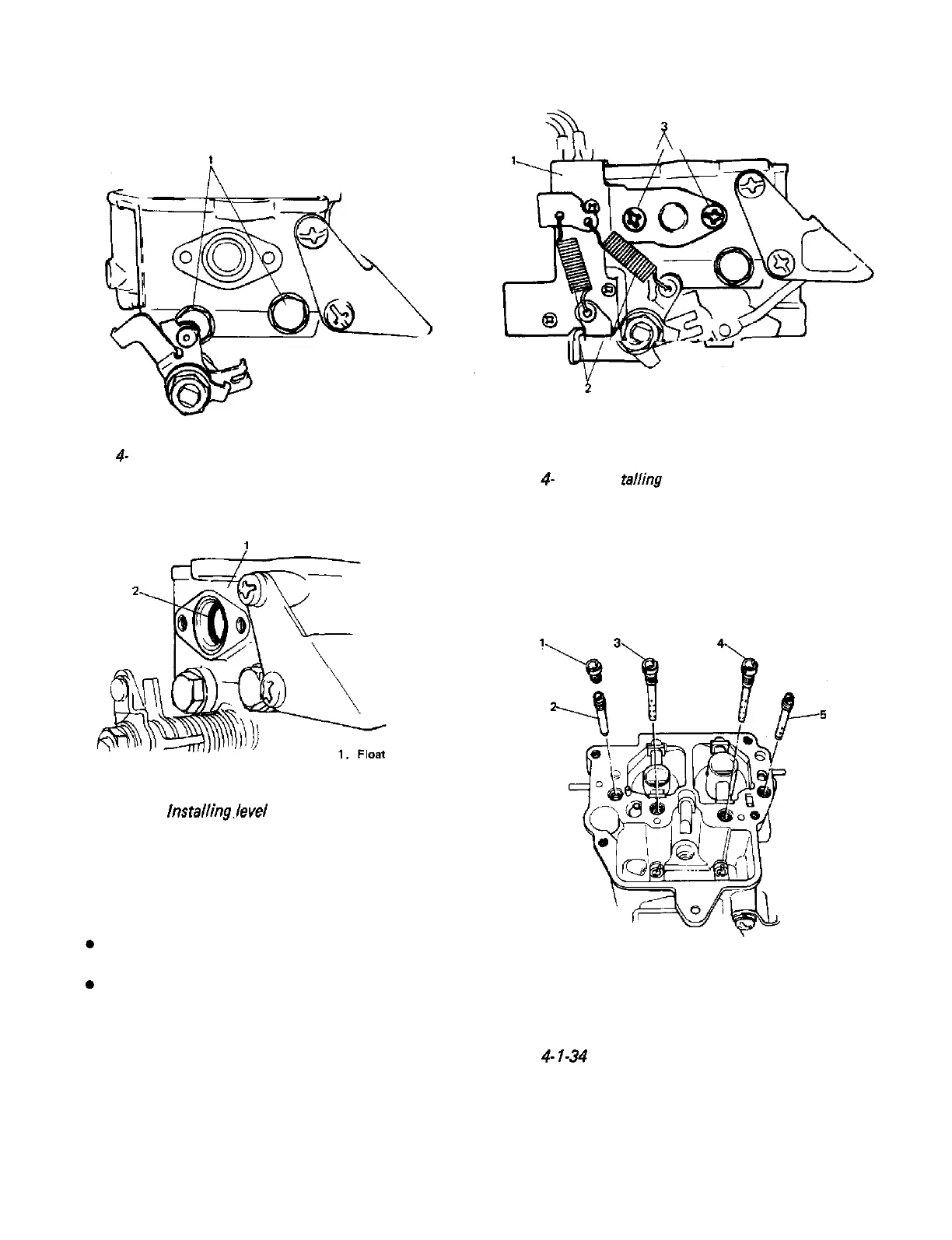
1. Drain plug
Fig.
4-
l-3 1 Installing drain plugs
6) Install level gauge seal.
chamber
2.
Level gauge seal
Fig. 4-l-32
lnstalling.level
gauge seal
7) install micro switch bracket with micro
switches and level gauge, and two springs
as shown in below figure.
NOTE:
0
0
Don’t remove micro switches (idle switch &
wide open switch) from bracket.
When bracket with micro switches has been
removed from float chamber for any service
and reinstalled after service work, make sure
to check switches for operation and adjust
if necessary. Check and adjustment for micro
switches should be carried out with carbure-
tor removed from intake manifold.
Refer to SECTION 5 “EMISSION CONTROL
SYSTEM” for procedure to check and adjust
micro switches.
1. Micro switch bracket
2. Spring
3. screw
Fig,
4-
l-33
Ins
tailing
bracket and springs
8) Install jets and air bleeders to float chamber.
Refer to Fig. 4-l -34 for their installation.
1.
Primary slow air No. 2 bleeder
2.
Primary slow jet
3.
Primary main air bleeder
4.
Secondary main air bleeder
5.
Secondary slow jet
Fig.
4-
l-34
Installing jets and air bleeders
4-17
 Loading...


