The alternator features a solid state regulator
that is mounted inside the alternator. All regula-
tor components are enclosed into a solid mold,
and this unit along with the brush holder assemb-
ly is attached to the slip ring end frame. The
regulator voltage setting cannot be adjusted.
The alternator rotor bearings contain enough
grease to eliminate the need for periodic lubri-
cation. Two brushes carry current through the
two slip rings to the field coil mounted on the
rotor, and under normal conditions will provide
long period of attention-free service.
The
stator
windings are assembled on the inside
of a laminated core that forms part of the
alternator frame. A rectifier bridge connected
to the
stator
windings contains six diodes,
and electrically changes the
stator
A.C. voltages
to a D.C. voltage which appears at the generator
output terminal.
The neutral diodes serve to convert the voltage
fluctuation at the neutral point to direct current
for increasing the alternator output.
A condenser mounted in the end frame protects
the diodes from high voltages and suppresses
radio noise.
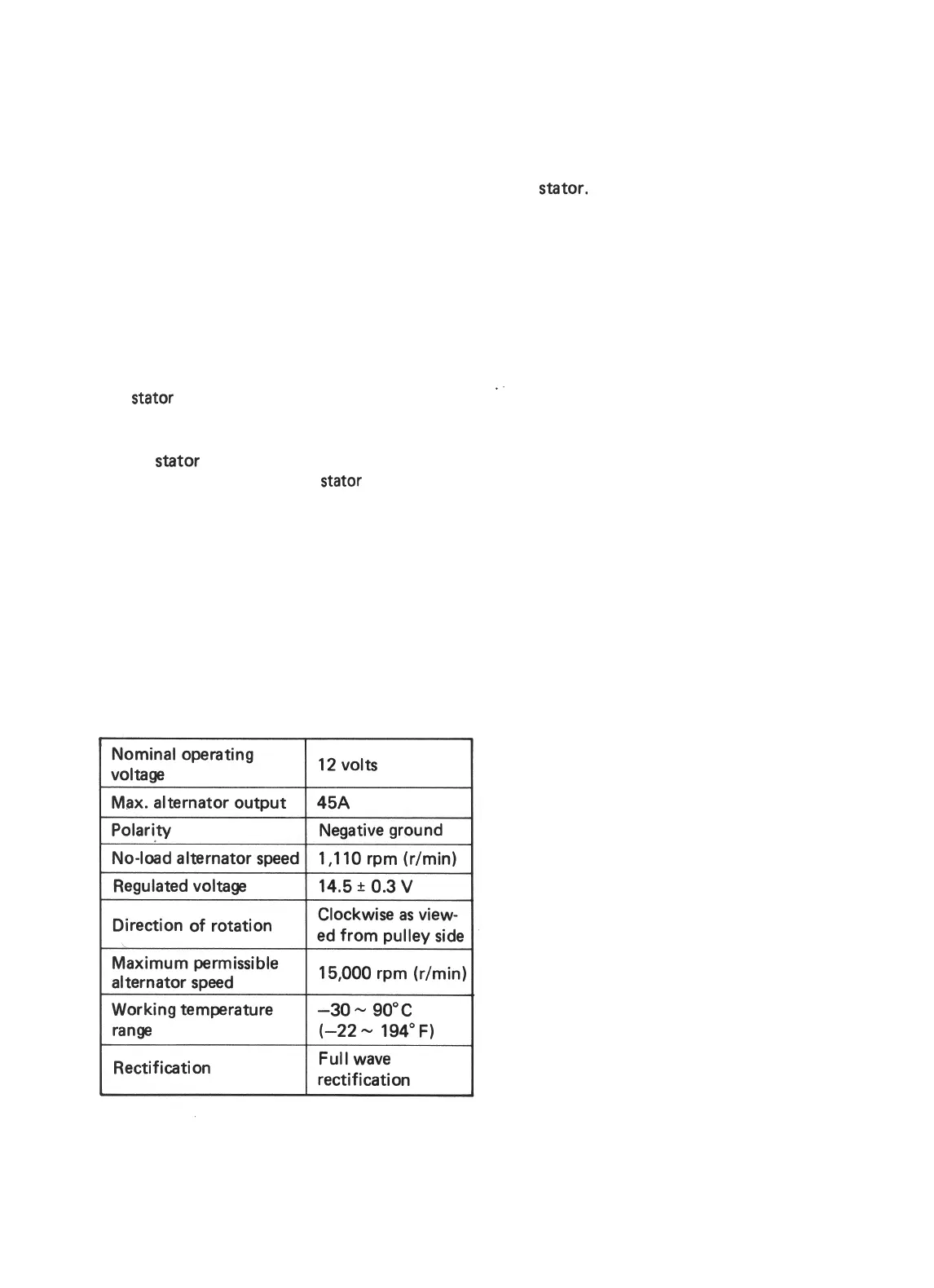
DATA AND SPECIFICATION
Nominal operating
voltaga
Max. alternator output
12 volts
45A
No-load alternator speed
I
Direction of rotation
Clockwise as view-
ed from oullev side
Maximum permissible
alternator speed
Working temperature
range
Rectification
15,000 rpm
(r/min)
-3o-
90°C
(-22
-
194”
F)
Full wave
rectification
Noisy Alternator
Noise from the alternator may be caused by a
loose drive pulley, loose mounting bolts, worn
or dirty bearings, defective diode, or defective
stator.
DIAGNOSIS
A charging circuit wiring diagram for alternator
connection is shown above. To avoid damage,
always follow these precautions:
1) Do not mistake the polarities of IG terminal
and L terminal.
2) Do not create short circuit between IG and
L terminals. Always connect these terminals
through a lamp.
3) Do not connect any load between L and E.
Trouble in the charging system will show up
as one or more of the following conditions:
a.
Faulty indicator lamp operation.
b. An undercharged battery as evidenced by
slow cranking or indicator clear with red
dot.
c. An overcharged battery as evidenced by
excessive spewing of electrolyte from the
vents.
10-3
 Loading...


