16-3. DISASSEMBLY
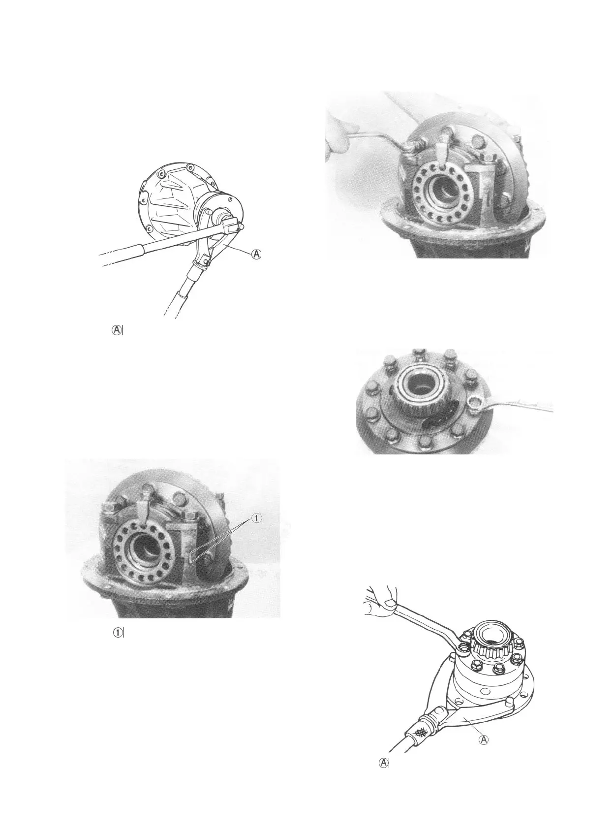
Lock flange immovable by using special tool,
and remove nut from the end of bevel pinion
shank.
Fig. 16-12 @ Special tool (Rotor holder 09930-
40 113)
Scribe marks on each cap bolted to the saddle
portion of carrier case and holding down the
side bearing. The marks are to identify caps.
This means that there are right and left caps, so
identified and so handled at the time of reas-
sembly.
Fig. 16-13 @ Scribed match marks
At each side, loosen bolts on bearing adjuster
stopper,
remove bearing cap securing bolts,
and take off cap. Lift differential case assembly,
complete with bevel gear, off the carrier.
Fig. 16-14
Remove 10 bolts securing bevel gear to diffe-
rential case, and separate gear from case.
Fig. 16-15
There are 8 bolts fastening two differential
case halves together. Remove these bolts to
sever right-hand case half from left-hand one,
and take off right-hand one.
Fig. 16-16 @ Special tool (Rotor holder
09930-40 113)
16-6
 Loading...


