l
Connecting rod alignment:
Mount connecting rod on aligner to check
it for bow and twist and, if either limit is
exceeded, replace it.
Limit on bow 0.05 mm (0.0020 in.)
I
Limit on twist
)
0.10 mm (0.0039 in.)
1
Crank Pin and Connecting Rod Bearings
l
Inspect crank pin for uneven wear or damage.
Measure crank pin for out-of-round or taper
with a micrometer. If crank pin is damaged,
or out-of-round or taper is out of limit,
replace crankshaft or regrind crank pin to
undersize and use undersize bearing.
I
Connecting
rod bearing size
Crank pin diameter
I
I
Standard
41.982
-
42.000 mm
(1.6529
-
1.6535 in.)
I
0.25 mm (0.0098 in.) 41.732
-
41.750 mm
undersize
(1.6430
-
1.6437 in.)
Out-of-round and
taper limit
0.01 mm (0.0004 in.)
l
Rod bearing:
Inspect bearing shells for signs of fusion,
pitting, burn or flaking and observe contact
pattern. Bearing shells found in defective
condition must be replaced.
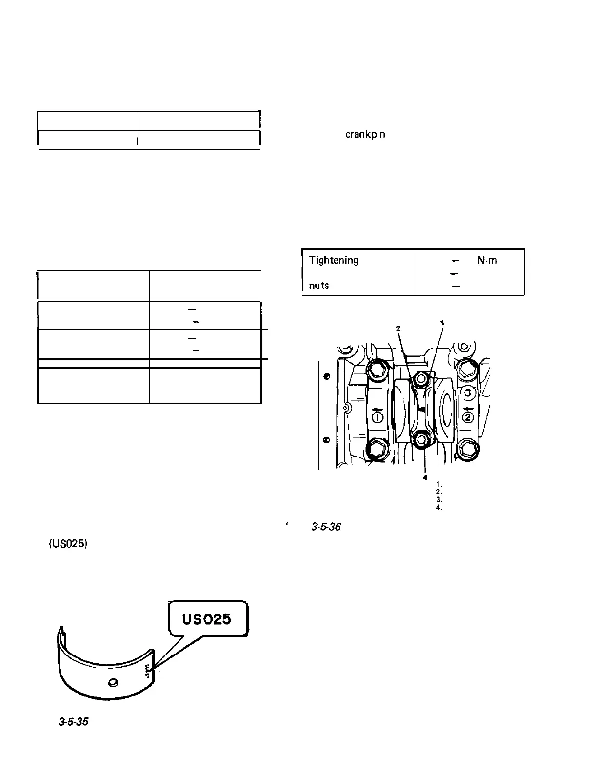
Two kinds of rod bearing are available;
standard size bearing and 0.25 mm under-
size bearing. To distinguish them, 0.25 mm
undersize bearing
has stamped number
(USO25)
on its backside as indicated in Fig.
3-5-35, but standard size one has no such
number.
l
Rod bearing clearance :
1) Before checking bearing clearance, clean
bearing and crank pin.
2) Install bearing in connecting rod and bear-
ing cap.
3) Place a piece of gaging plastic the full width
of the
crankpin
as contacted by bearing
(parallel to the crankshaft), avoiding the oil
hole.
4) Install rod bearing cap to connecting rod.
When installing cap, be sure to point arrow
mark on cap to crankshaft pulley side, as
indicated in Fig. 3-5-36. Tighten the cap
nuts to the specified torque, DO NOT turn
crankshaft with gaging plastic installed.
torque
33
-
37
N-m
for
rod bearing
cap
3.3
-
3.7 kg-m
24.0
-
26.5 lb-ft
e
3
0
.
’
Fig.
3-5-36
Installing bearing cap
Rod bearing cap
Arrow mark
Crankshaft pulley side
Cap nut
Fig.
3-5-35
0.25 mm undersize bearing
3-28
 Loading...


