Assembly
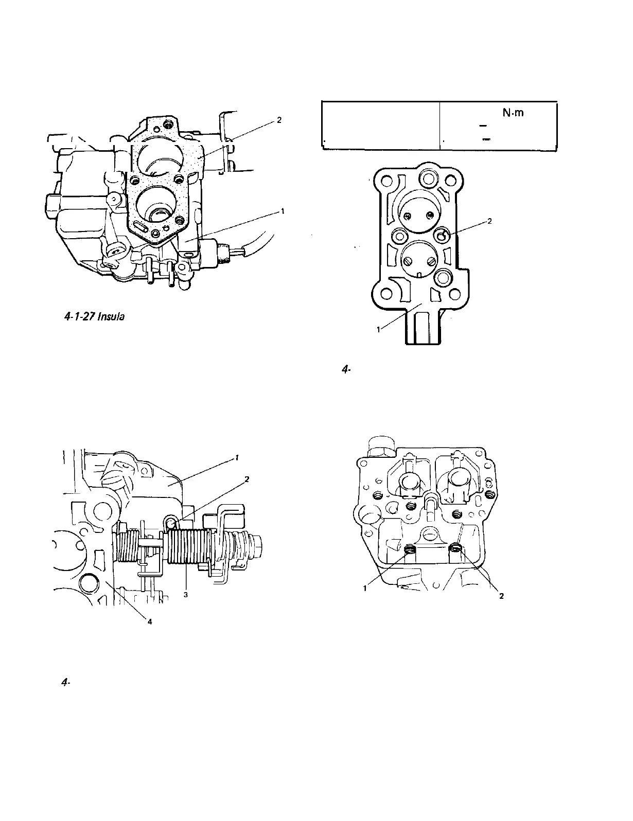
1) Install insulator to float chamber as shown in
below figure.
1. Float chamber
2. Insulator
Fig.
4-
l-27
lnsula
tor installation
2) After attaching both ends of throttle lever
return spring as shown in figure, install
throttle chamber to float chamber. Hook
throttle valve side end of return spring over
the boss on float chamber as shown in below
figure.
3) Install spring washer as below figure, and
torque four screws to specification.
Tightening torque
for screws
4-7
N-m
0.4
-
0.7 kg-m
3
-
5 lb-ft
1. Throttle chamber
2. Spring washer
Fig.
4-
l-29 Installing washer
4) Install primary and secondary main jets.
1. Float chamber
2. Boss
3. Throttle lever return spring
4. Throttle chamber
Fig.
4-
l-28 Hooking throttle lever return spring
1. Primary main jet
2. Secondary main jet
Fig. 4-I-30 Primary and secondary main jets
4-16
 Loading...


