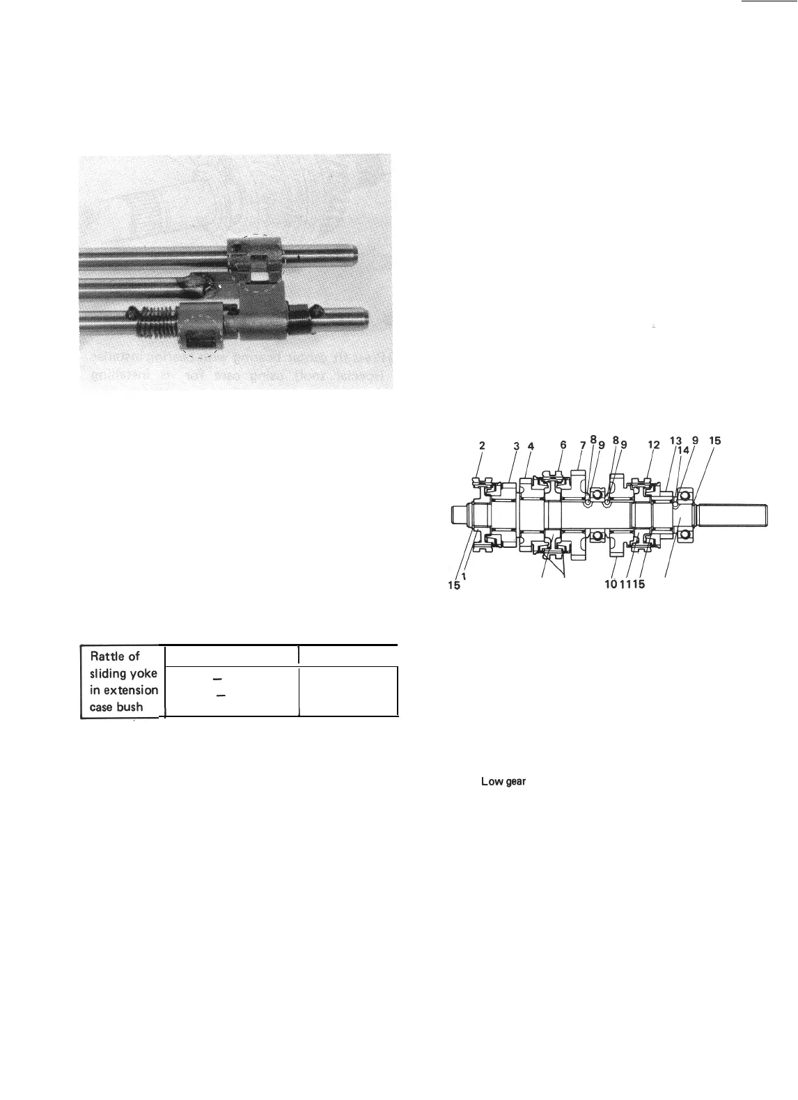
Gear Shift Shafts
Check the part of shaft as indicated in below
figure for uneven wear. Replace shaft if uneven
wear is noted.
Fig. 13-40
Extension Case Bush
Check bush press-fitted in extension case for
wear by measuring radial clearance between
bush bore and sliding yoke. If sliding yoke
rattles in bush because of advanced wear it will
cause propeller shaft to rattle. For this reason,
an extension case found to allow its sliding
yoke to rattle in excess of service limit must be
replaced; replacement of bush alone is not
permissible.
Rattle of
sliding yoke
c
in extension
case bush
Standard
1
Service limit
0.025
-
0.089 mm
0.2 mm
(0.0010
-
0.0035 in.)
(0.0078 in.)
I
I
I
13-6. IMPORTANT STEPS IN
INSTALLATION
NOTE:
l
Before installation, wash each part and apply
specified gear oil to sliding faces of bearing
and gear.
l
Use new circlips on shaft for reinstallation.
Don’t reuse used circlips.
l
Tighten each fastening bolt and nut according
to specified torque data listed on the last
page of this section.
Main Shaft and Input Shaft
:,
Install each parts by reversing respective removal
procedures. Be careful for installing direction of
each washer, gear, synchronizer hub and sleeve.
Refer to figure below. Make sure to install each
ball on main shaft.
5 17
la
1.116
16
1. High speed synchronizer
hub
2. High speed synchronizer
sleeve
3. 3rdgear
4.
2ndgear
5. Low speed synchronizer
hub
6. Low speed synchronizer
sleeve
7.
Lowgear
6.
Washer
9.
Ball
10.
Reverse gear
11. Reverse synchronizer
hub
12.
Reverse synchronizer
sleeve
13.
5th gear
14. 5th gear washer
15. Circlip
16.
Main shaft
17.
Spring
Fig. 13-4 1
13-15
 Loading...


