[Gauge unit]
21-6. FUEL LEVEL METER AND GAUGE
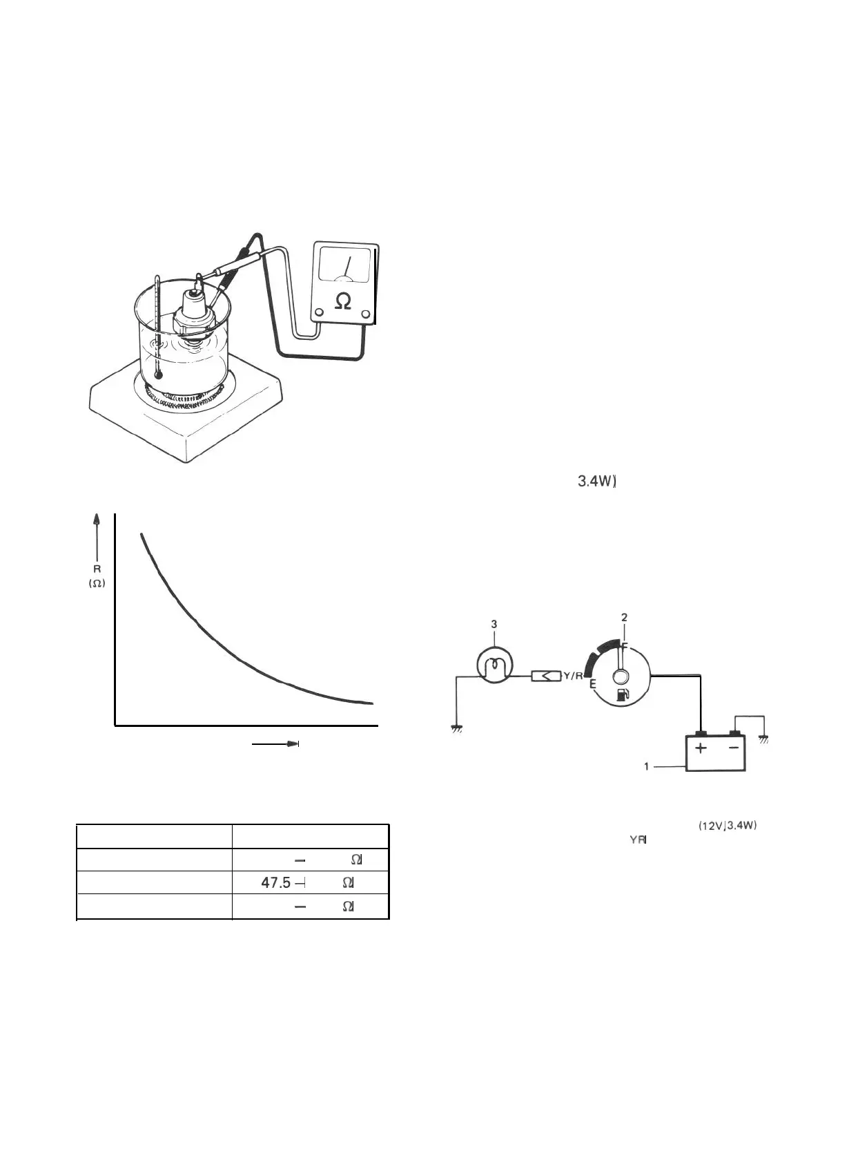
Warm up gauge unit. Thus make sure its resis-
tance is decreased with increase of temperature.
Temperature and resistance relationship can be
plotted in a graph as shown below.
The fuel level meter circuit consists of the fuel
level meter installed inside the combination
meter and the fuel level gauge installed to the
fuel tank.
Fig. 21-17
w
Temp.
Fig. 21-18 Resistance- Temp. Relationship
Temperature
50°C (122°F)
80°C (176°F)
100°C (212°F)
Resistance
133.9
-
178.9
f-i
47.5-
56.8
!a
26.2
-
29.3
52
Current flowing through the meter coil is
changed to control the meter pointer. That is,
when fuel is full, the fuel level gauge unit
resistance is decreased with more current flowing
into the meter coil, causing the meter pointer
to point at the “F” position.
INSPECTION
[Fuel level meter]
1. Disconnect Y/R (Yellow/Red) lead wire
going to gauge unit.
2. Use a bulb (12V 3.4W) in position to ground
above lead wire as illustrated.
3. Turn ignition switch ON.
Make sure the bulb is lighted and meter
pointer fluctuates several seconds thereafter.
If meter is faulty, replace it.
Fig. 21-19
1. Battery
2. Fuel level meter
3. Test lamp
(12V.
3.4%‘)
YR
: Yellow/Red
NOTE:
Wind sealing tape on screw threads of gauge
before installing gauge to intake manifold.
21-12
 Loading...


