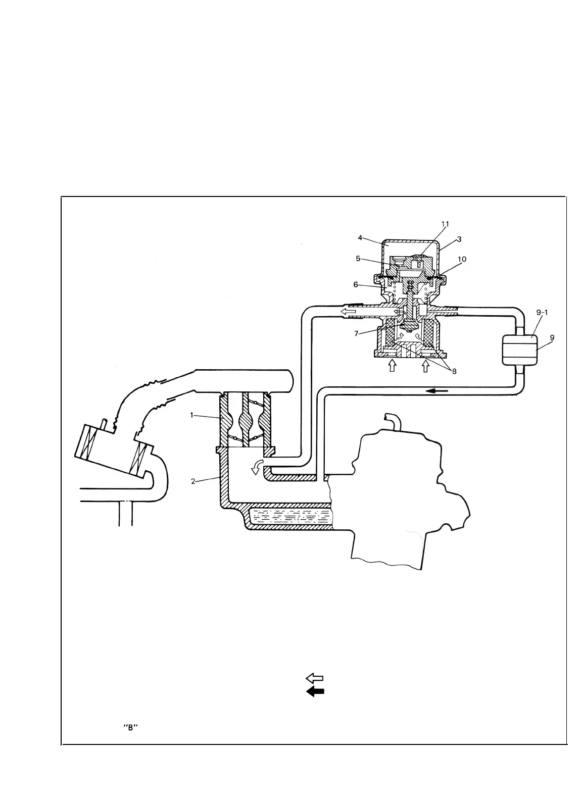
DECELERATION MIXTURE CONTROL SYSTEM
This system consists of a MCV (Mixture Control Valve), jet and vacuum hoses.
This system is designed to introduce fresh air into the intake manifold to reduce generation of excessive
HC and CO emission caused by temporary rich air-fuel ratio while rapid deceleration.
The MCV has a pressure balancing orifice and check valve on its diaphragm, and closes when manifold
vacuum is constant. As manifold vacuum increases according to rapid deceleration, manifold vacuum
applies to MCV chamber “B” through jet, the MCV opens and introduces fresh air into the intake mani-
fold. When manifold vacuum becomes constant, pressure difference between two sectioned chambers “A”
and “B” gradually diminishes through pressure balancing orifice, then the MCV closes.
1.
Carburetor
7. Valve
2. Intake manifold 8. Filter
3.
MCV
9. Jet (Colorless)
4.
Chamber “A”
9-1. Gray side
5.
Orifice
10. Diaphragm
8.
Chamber
“B”
11. Check valve
Fresh air
c=l
1
Vacuum
Fig. 5-l-7
Deceleration mixture control system
5-9
 Loading...


