MAINTENANCE
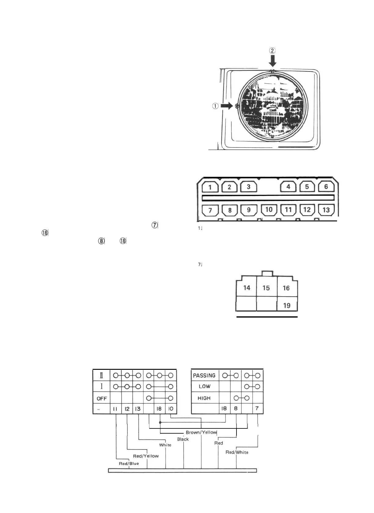
(1) Headlight adjustment
There are two screws (1)and (2)which can be
used for adjustment. Use these screws to
adjust the headlight position for the vertical
and horizontal alignment of each beam.
(2) Head light dimmer switch
Using circuit tester, check each circuit for
continuity by putting tester probe pins to
the terminals shown in Fig. 21-7. With switch
kept in LOW BEAM position, tester should
indicate continuity between terminals
0
and
@
. Similarly, there should be continuity
between terminals
@
and
@
when in HIGH
BEAM position.
Fig. 21-6
Switch connector
1
”
m
m
m
m
-
J
1.
Green/Red (Green/Black)
8.
Red
2. Green/Yellow
9. Blue/Green
3.
Green
10. Brown/Yellow
4. Yellow
11. Red/Blue
5.
White/Blue
12. Red/Yellow
6. Yellow/Blue
13. White
7.
Red/White
1
17
1
18
1
19
1
14. Yellow/White
15.
Blue
16. Blue/Red
Fig. 21-7
17.
Blue/Black
18. Black
19. Blue/White
Combination switch (Lighting switch circuit)
Fig. 27-8
I I
I
I
I
,
Brown(Yellow
21-6
 Loading...


