THROTTLE VALVE
INDICATOR
POSITION
MOVEMENT
Idle position
Swing
l/2
open
Stay after deflection
Full open
Swing
NOTE:
If indicator doesn’t deflect at all, reverse above
connection, that is, negative prod to body and
positive one to check terminal, and carry out the
same check.
Fig.
53-
18
1.
Check terminal
If check results are not satisfactory, check idle
and wide open micro switches as follows or their
circuits for continuity referring to item “check-
ing sensors and their lead wires
”
(p. 5-32).
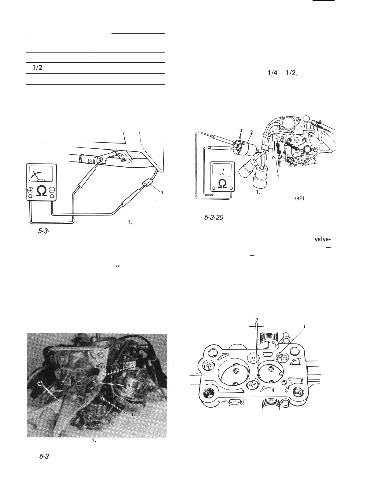
[Idle micro switch]
1) Remove carburetor following normal service
procedures.
2) Turn fast idle cam counterclockwise and
insert a suitable pin available then into
holes in cam and bracket to lock the cam.
1,
Fast idle cam
3. Pin
2. Bracket
4. Plier
3) Connect ohmmeter to terminals of idle micro
switch. Check for continuity between termi-
nals. When throttle valve is at idle position,
ohmmeter should indicated “zero” ohm.
4) Open throttle valve by
l/4
to
l/2,
and ohm-
meter indicator should indicate infinity.
If check results in steps 3) and 4) are not
satisfactory, replace idle micro switch with a
new one.
1.
idle micro switch
2. Green coupler (4P)
3. idle micro switch’s terminals
(Green/White and Black wires)
Fig. 5-3-20 Connecting ohmmeter to idle micro
switch
5) Open throttle valve slowly till throttle
valve-
to-carburetor bore clearance becomes 0.36
-
0.62 mm (0.014
-
0.024 in) and check that
ohmmeter indicator moves from “zero” ohm
to infinity then.
If the above indicator movement does not
occur within specified range, make adjust-
ment by bending lever shown in below figure.
Bend lever down when clearance is below
specification and up when over specification.
n
1. Primary throttle valve
2. Clearance
Fig. 5-3-21 Clearance between throttle valve
and carburetor bore
Fig. 5-3- 19
5-24 4
 Loading...


