Crankshaft Main (Journal) Bearings
General informations:
l
Service main bearings are available in
standard-
size and 0.25 mm (0.0098 in) undersize, and
each of them has 5 kinds of bearings differ-
ing in tolerance.
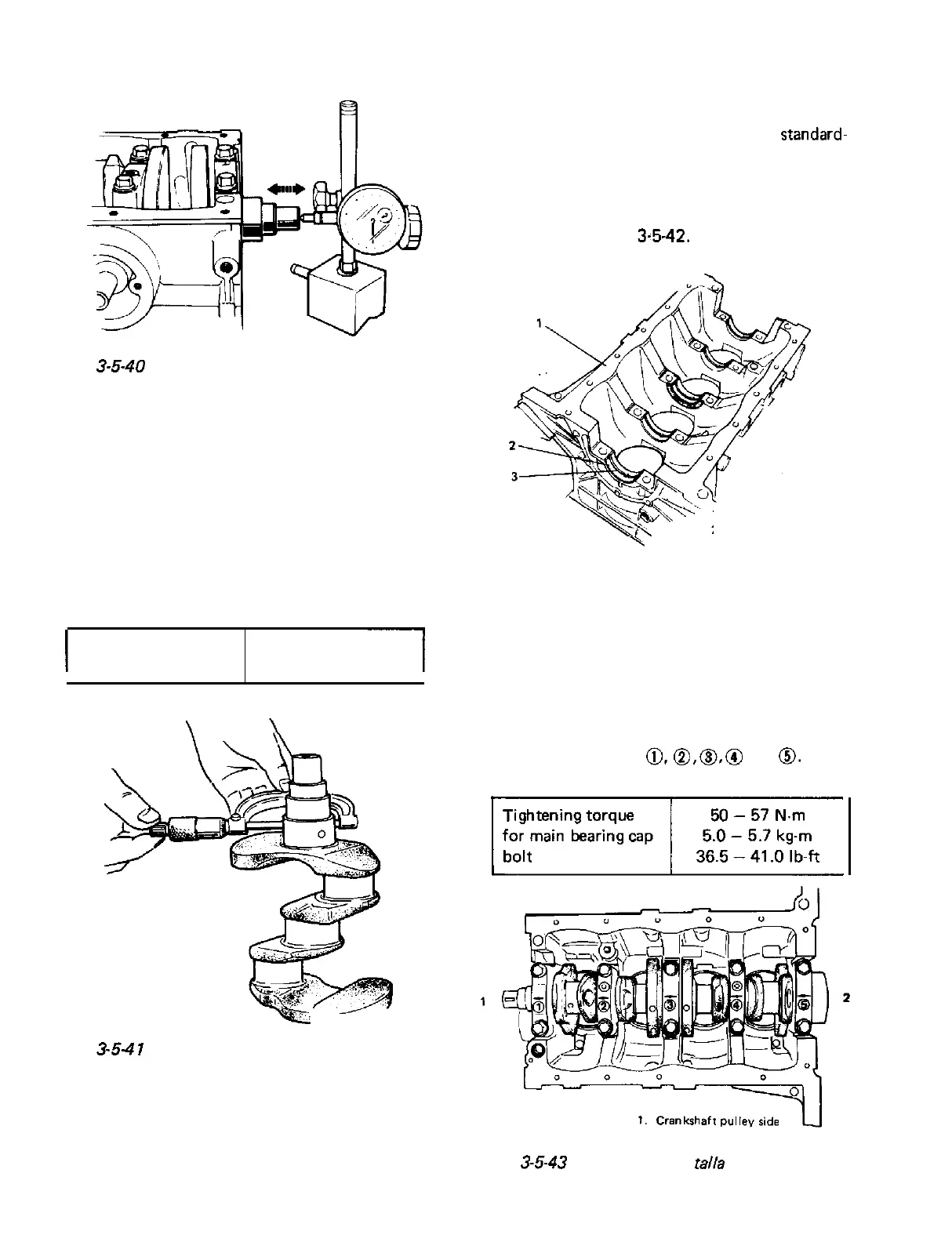
l The upper half of bearing has oil groove as
indicated in Fig.
3~5-42.
Install this half with
oil groove to cylinder block.
Fig.
3-5-40
Measuring thrust play of crankshaft
l
Out-of-round and taper (uneven wear):
An unevenly worn crankshaft journal shows
up as a difference in diameter at a cross
section or along its length (or both). This
difference, if any, is to be determined from
micrometer readings.
If any of journals is badly damaged or if the
amount of uneven wear in the sense explained
above exceeds its limit, regrind or replace the
crankshaft.
I
Limit on out-of-round
and taper
0.01 mm (0.0004 in.)
Fig. 3-5-4
1
Checking uneven wear
1. Cylinder block
2. Upper half of bearing
3.
Oil groove
Fig. 3-5-42 Upper half of bearing installation
l On each main bearing cap, arrow mark and
number are embossed as indicated in Fig.
3-5-43.
When installing each bearing cap to cylinder
block, point arrow mark toward crankshaft
pulley side and install each cap from crank-
shaft pulley side to flywheel side in ascending
order of numbers
@,a,
0,
@
and
0.
Tigh-
ten cap bolts to specified torque.
3
2. Flywheel side
Fig.
3-5-43
Bearing caps ins
talla
tion
3-30
 Loading...


