Fig. 13-67
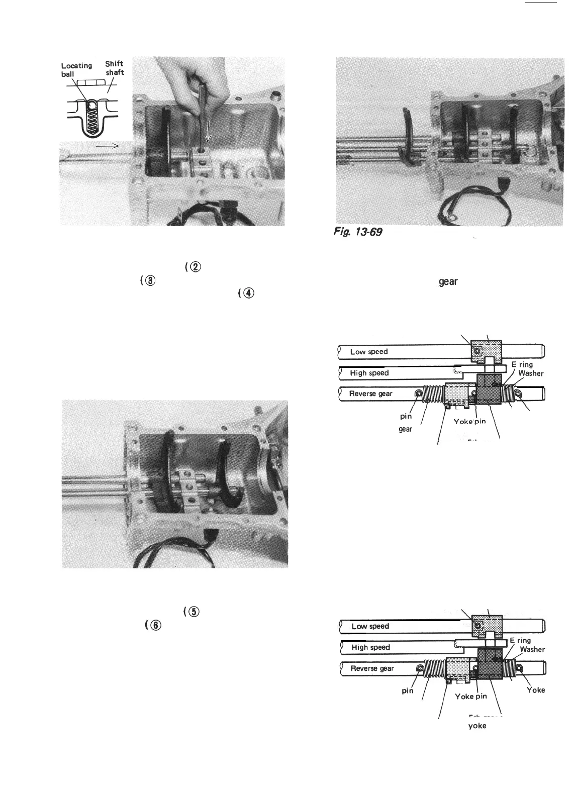
4) Install interlock ball
(
@
in Fig. 1364) and
locating ball
(
@
in Fig. 13-64) in upper case.
After installing interlock roller
(
@ in Fig.
1364) in high speed gear shift shaft and
insert shaft into upper case as described in
2) and 3).
Fork should be installed in such direction as
shown in Fig. 13-68. Then drive shift yoke
pin until it becomes flush with outer surface
of fork.
Fig. 13-68
5) Install interlock ball
(
@ in Fig. 1364) and
locating ball
(
@ in Fig. 13-64) into upper
case. Then insert reverse gear shift shaft
into upper case as described in 2) and 3).
[Yokes]
1) Install low speed
.gear
shift yoke as shown
below, using care for its direction.
Low speed ear shift yoke
Yoke pin
3
%-JJ
Yoke pit!
\
\
Yoke pin
Reverse
gaar
shift
5th gear select
lim spring
return spring
5th gear shift
Reverse gear shift yoke
lim yoke
Fig. 13-70
2) Install reverse gear shift yoke and 5th gear
shift yoke as shown below. Use care for
installing direction of each part.
Between 2 springs, shorter one is 5th select
return spring.
Low speed ear shift yoke
Yoke pin
3
Yoke
pi,/
I
\
;oke
pin
Reverse gear shift
5th gear select
lim spring
return spring
5th gear shift
Reverse gear shift
yoke
lim yoke
Fig. 13-71
13-21
 Loading...


