3) install piston and connecting rod assembly
into cylinder bore.
@Apply engine oil to pistons, rings, cylinder
walls, connecting rod bearings and
crank-
pins.
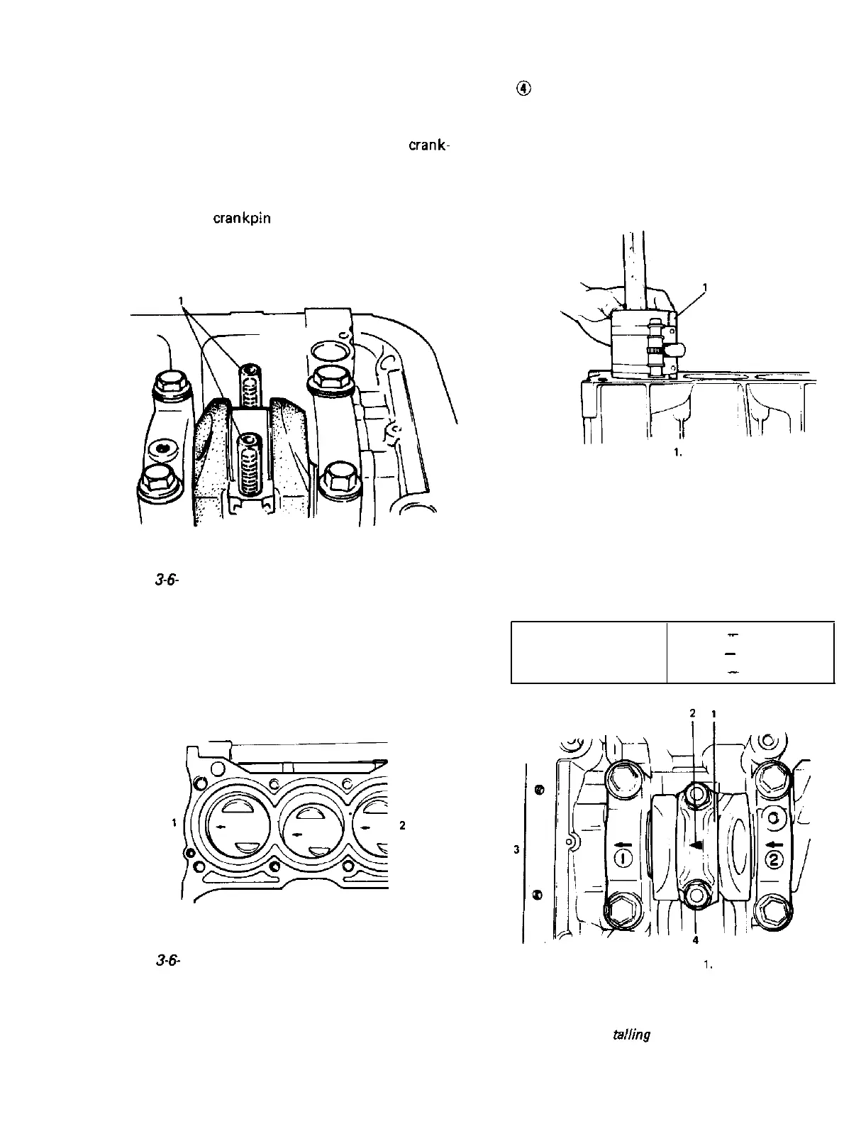
@Put guide hoses over connecting rod bolts as
shown in Fig. 3-6-18. These guide hoses
protect
crankpin
and thread of rod bolt
from damage during installation of connect-
ing rod and piston assembly.
1. Guide hoses
Fig.
3-6-
18 Guide hoses installation
@When installing piston and connecting rod
assembly into cylinder bore, point arrow
mark on each piston head to crankshaft
pulley side.
1. Crankshaft pulley side
2. Flywheel side
Fig.
3-6-
19 Direction of arrow mark on
piston head
@ Use piston ring compressor (Special tool) to
compress rings. Guide connecting rod into
place on the crankshaft.
Using a hammer handle, tap piston head to
install piston into bore. Hold ring compres-
sor firmly against cylinder block until all
piston rings have entered cylinder bore.
1.
Piston ring compressor
(Special tool 09916-77310)
Fig. 3-6-20 Installing piston to cylinder
4) Install connecting rod bearing cap.
When installing cap to rod, point arrow mark
on cap to crankshaft pulley side.
Tighten cap nuts to specification.
Tightening torque 33
-
37 N-m
for rod bearing
3.3
-
3.7 kg-m
cap nuts
24.0
-
26.5 lb-ft
1.
Bearing cap
2. Arrow mark
3. Crankshaft pulley side
4. Cap nut
Fig. 3-6-21
Ins
tailing
bearing cap
3-41
 Loading...


