NOTE:
1
kerns
1, 5,6, 7 and 6 are in
special tad
(09910-36210).
1. Driver handle
2. Piston pin
3.
Piston
4. Connecting rod
5. Piston pin guide
6. Guide spring
7. Spring retainer
8.
Base
9. Support
Fig. 3-G
14
Ins tatting piston pin
@
Press piston pin until line marked on driver
handle is flush with flat surface of piston
(Fig. 3-6-l 5).
1.
Driver handle
2. Line
3. Piston
4. Piston pin
Fig.
3-6-
15 Line marked on driver handle
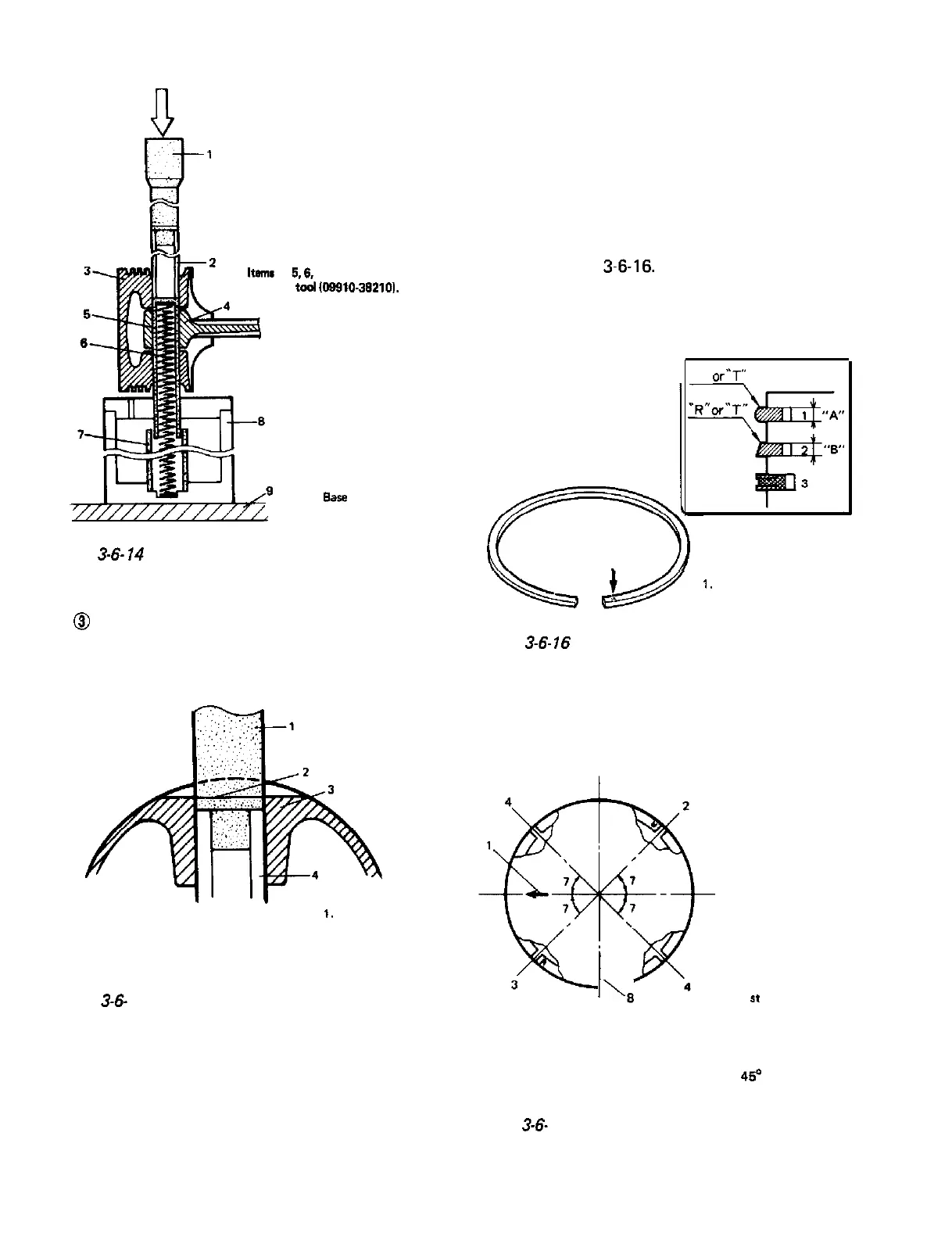
2) Install piston rings to piston.
l As indicated in Fig. 3-6-16, 1st and 2nd
rings have “R” or “T” mark. Installing these
piston rings to piston with marked side of
each ring faced foward top of piston.
l 1st ring differs from 2nd ring in thickness,
shape and color of the surface contacting
cylinder wall.
Distinguish 1st ring from 2nd ring by refer-
ring to Fig. 3-6-16.
l When installing oil ring, install spacer first
and then two rails.
“R”
or”
T”
1.
1st ring (“A” 1.2 mm)
2. 2nd ring (“6” 1.5 mm)
3. Oil ring
Fig.
3-6-
16
Piston rings installation
l After installing 3 rings (lst, 2nd and oil
rings), distribute their end gaps as shown
in Fig. 3-6-l 7.
5
1.
Arrow mark
I\,
6
2.
1
st
ring end gap
3. 2nd ring end gap
4.
Oil ring rail gaps
5.
lnta ke side
6. Exhaust side
7. 450
8. Oil ring spacer gap
Fig.
3-6-
17 Piston ring end gaps positions
3-40
 Loading...


