BOOSTER ASSEMBLY
[GENERAL DESCRIPTION]
The booster is located between the master cylinder and the brake pedal. It is so designed that the force
created when the brake pedal is depressed is mechanically increased combined with the engine vacuum.
The booster has a diaphragm of
4
180 mm effective diameter. Its operation is described in the following pages.
NOTE:
Use all components included in repair kits to service this booster. Lubricate rubber parts, where indicat-
ed, with silicone grease provided in kits. The torque values specified are for dry, unlubricated fasteners.
If any hydraulic component is removed or brake line disconnected, bleed the brake system.
Never lubricate any hydraulic component with silicone grease.
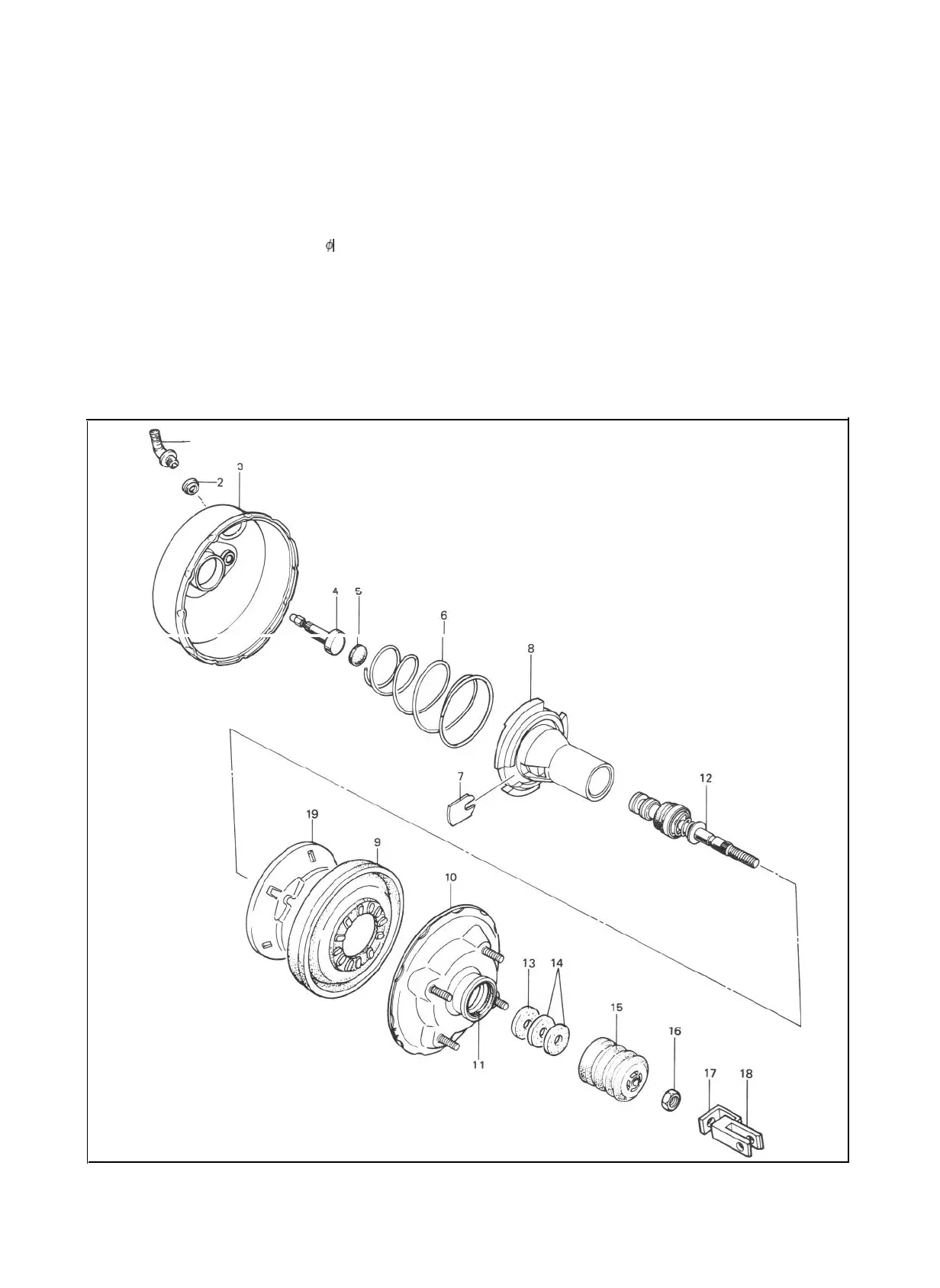
1
1.
Vacuum check valve
11.
No. 2 body oil seal
2.
3.
Grommet
12.
Booster air valve assembly
Booster No. 1 body
13.
Air cleaner
separator
4. PistonRod
14.
Air cleaner element
5. Reaction disc
15.
Body boot
6. Booster piston return
spring
16.
Nut
7. Valve stopper key
17.
Bracket
8. Booster piston
18.
Push rod clevis
9. Diaphragm
19.
Pressure plate
10. Booster No. 2 body
Fig.
19-12
19-11
 Loading...


