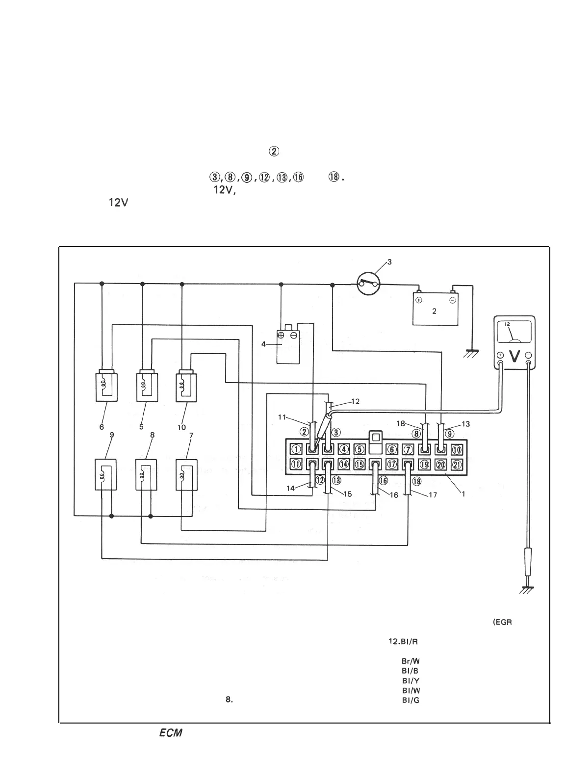
[Checking ECM power circuits]
Connected to the ECM are the ignition coil and solenoids or solenoid valves. If a disconnection or a
failure of contact occurs within a circuit (power circuit) including any of these coil or solenoids or sole-
noid valves, signals will not be sent to the ECM and as a result, the feed back system will not operate
properly. Therefore, check the power circuits according to the following procedure.
1) Disconnect the coupler connected to the ECM.
2) Turn ON the ignition switch but be sure not to run the engine.
3) Connect a voltmeter between the terminal
@
of the disconnected coupler (on the wiring harness side)
and the body (ground) as shown in below figure and measure the voltage. And then repeat the same
with each of the terminals
0,
0,
0,
0,
8,
@
and
0.
If the measured voltage between each
terminal and the body is about
12V,
each circuit is in good condition.
4) If about
12V
is not obtained in the above check, the particular circuit may be disconnected or out of
contact. Check the circuit for such conditions.
5) After checking, connect the coupler to ECM securely.
.
1. Coupler (Viewed from wire harness side)
10. Three way solenoid valve
(EGR
system)
2. Battery 11. Br (Brown) lead wire
3. Ignition switch (ON)
!2.
BI/R (Blue/Red) lead wire
4. Ignition coil 13. B/W (Black/White) lead wire
5. Vacuum switching valve
14.
Br/W
(Brown/White) lead wire
(secondary throttle valve)
15. BI/B (Blue/Black) lead wire
6. Three way solenoid valve (Idle-up)
16.
BI/Y
(Blue/Yellow) lead wire
7. Mixture control solenoid
17. BI/W (Blue/White) lead wire
8. Switch vent solenoid
18. BllG (Blue/Green) lead wire
9. Fuel cut solenoid valve
Fig. 5-3-42 Checking ECM power circuits
 Loading...


