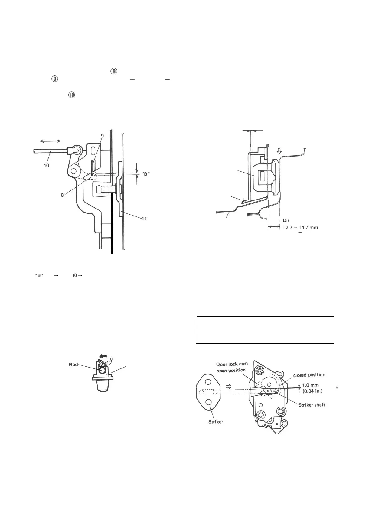
[Door lock inside handle]
Fit the inside handle, adjusting the clearance
between inside open lever
@I
and outside open
lever
@I
of the door lock to 0
-
2 mm (0
-
0,079 in) by moving the inside handle remote
control rod
@
in the arrow direction given in
below figure.
After installation, give it a trial and check if its
play felt then is appropriate.
8. Inside open lever
9. Outside open lever
10. Control rod
11. Door lock striker
“B”
: 0
-
2 mm (0
-
0.079 in.)
Fig. 20-1-21
[Door lock rod pin]
Fix the lock rod with rod pin securely as illust-
rated below.
Rod pin
Fig. 20-1-22
[Door lock striker]
Increase or decrease striker spacers fitted in “A”
position behind the striker to adjust dimensions
to below values as shown in below figure.
After adjustment, check the difference in level
between the door and
there is difference by
striker to right or left.
body and adjust when
moving the door lock
Clearance
3.0 mm
(0.12 in.)
Spacer fitting position “A”
r
Striker
Door lock base
\JIA4Yl
y
<1
Door inner panel
Dimension
H
12.7-14.7mm
(0.499
-
0.579 in.)
Fig. 20-1-23
Move the striker base up and down so that
striker shaft aligns with the center of the groove
of the door lock (the clearance between the shaft
of door lock striker and lock base is 1.0 mm
(0.04 in.)) in the vertical direction.
CAUTION:
l
The striker should be placed vertically.
l Do not adjust the door lock.
Door lock cam
Fig. 20-1-24
20-7
 Loading...


