5.7.1.3 Clutch Solenoid Functions
This section along with Section 5.7.1.1: Clutch Basic Functions allows the adjustment of Clutch
Solenoid related items:
5.7.1.3.1 Function Code C5 – Shift Solenoid Type
This Function Code must be left at the default value unless a ZF-Hurth Gear is installed with
proportional Ahead and Astern Solenoids. When values 01 or 02 are selected, the current is
limited to the solenoids.
The available Values are:
00 - All Shift Solenoids except ZF-Hurth (DEFAULT)
01 - ZF-Hurth Proportional Solenoids with 12V Power
02 - ZF-Hurth Proportional Solenoids with 24V Power
The default value of 00 is used with most types of solenoids, with the exception of the ZF-
Hurth Gears with proportional Ahead and Astern solenoids.
To change the Value (Refer to Sections Section 5.2: Activating Set Up Mode and Section
5.3: Storing Values To Memory):
A Scroll to Function Code C5.
B Activate Set Up Mode.
C Scroll Up to change the Value.
D Store the Value to memory.
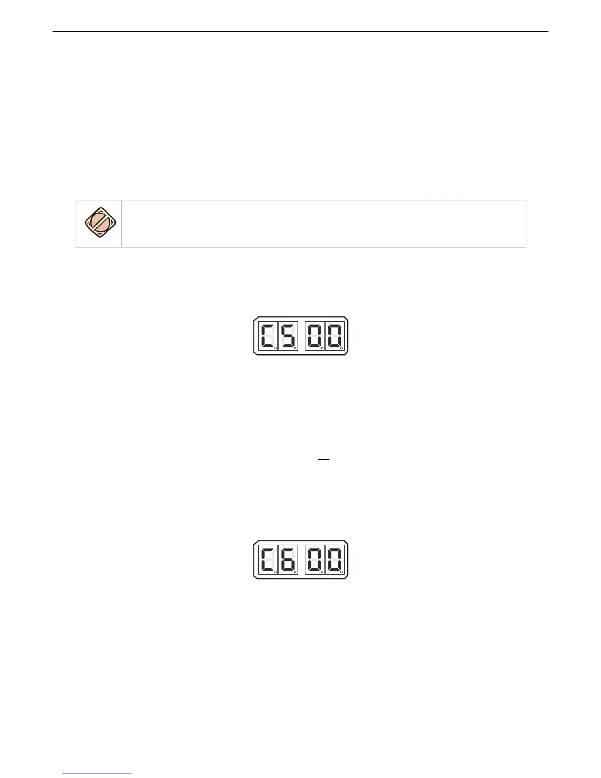
Figure 5-41: Display LED Function C5 Set Up Activated
5.7.1.3.2 Function Code C6 – ZF-Hurth Duty Cycle Ahead
This function adjusts the maximum current available to the Ahead Proportional Solenoid.
Failure to limit the current may result in permanent damage to the solenoid.
The available Values are 00.0 to 100.0 percent Duty Cycle of the applied voltage.
The Default Value is 100%.
To determine, and if required, change the Value (Refer to Sections Section 5.2: Activating
Set Up Mode and Section 5.3: Storing Values To Memory):
A Ensure that Troll is not
selected (no rapidly blinking LED).
B Connect an amp meter in series with the Ahead solenoid signal.
C Move the Control Head lever to the Ahead detent.
D Scroll to Function Code C6.
E Activate Set Up Mode.
F Scroll Up or Down until the appropriate maximum current level is reached.
G Store the Value to memory.
H Return the Control Head lever to the Neutral/Idle position.
Figure 5-42: Display LED Function C6 Set Up Activated
CAUTION: The maximum amount of current to these solenoids MUST be limited by the control system. Failure
to do so can cause permanent damage to the solenoids. Depending on the voltage applied to the solenoids,
adjust the Value to 01 for 12V power and 02 for 24V power.

 Loading...