10.1.1.5 9221 (Throttle Electronic, Clutch Solenoid, Troll Servo 2) Processor
The 9221 Processor is designed to precisely control speed, direction, and trolling valve on vessels
equipped with electronic Throttle, solenoid Clutch selection, and mechanical Troll selector.
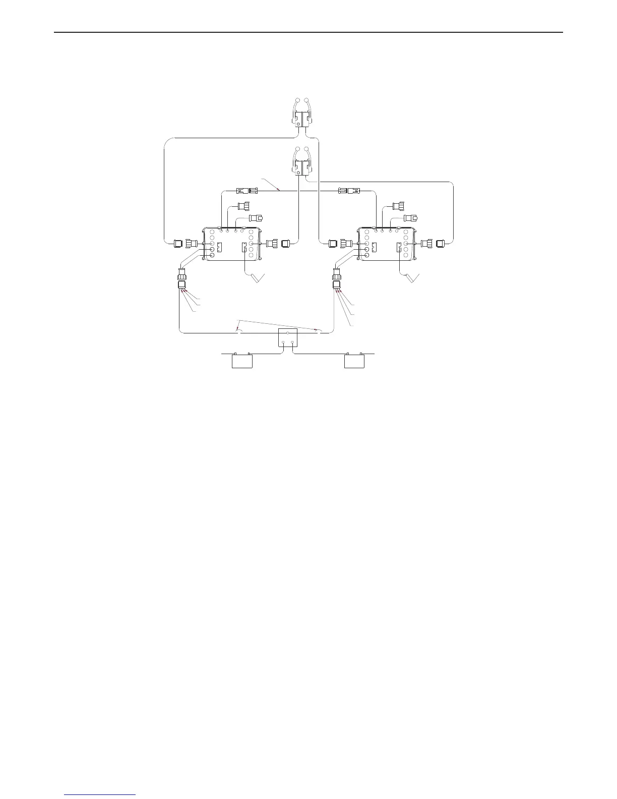
Figure 10-5: 9221 Basic Twin Screw, Two Station Diagram
10.1.2 Typical System Main Components
10.1.2.1 Control Head
The primary function of the Control Head is to send out a variable DC voltage to the Processor. This
DC voltage is representative of the Control Head’s present lever position. In addition to the primary
function, the Control Head also has audible (Sound Transducer) and visual (LED) status indications,
along with a Transfer Button for taking command and performing other system functions.
10.1.2.2 Processor
The Processor receives the variable DC voltage from the Control Head(s) and converts these inputs to
the appropriate electronic or electric outputs at the correct time and sequence to the Governor and
Gear Box. The information regarding throttle type, throttle/ clutch sequencing, etc., are all stored on
memory within the Processor.
10.1.2.3 Power Source
All electronic equipment must have power in order to operate. Ensuring a properly charged reliable
power source is available is crucial. The Processor requires a 12 or 24 VDC power system. The
minimum voltage at which the Processor will continue to operate is 8.00 VDC. The maximum allowable
voltage is 30 VDC. Exceeding these limits will not damage the Processor, but will render it unusable
temporarily. The power supply must be capable of delivering 10 amperes to each Processor on a
continual basis and current surges up to 20 amperes.
All cable calculations should be based on a 10 ampere draw with no more than 10% voltage drop.
33C PUSH/PULL CABLE
STBD
STATION 2
STATION 1
PORT
12297
SERIAL COMMUNICATION
10 AMP CIRCUIT BREAKERS
(BY OTHERS)
COMMON
GROUND
COMMON
GROUND
+
-
+
-
APS
CLUTCH PRES.
START INTERLOCK
ALARM
START INTERLOCK
CLUTCH PRES.
ALARM
TACH 1 TACH 1
THROTTLETHROTTLE
TROLL
MAX
SLIP
MIN
SLIP
TROLL
33C PUSH/PULL CABLE
MAX
SLIP
MIN
SLIP

 Loading...