10 Troubleshooting
10.1 General
The ClearCommand Control System consists of one Processor per engine, typically mounted in the engine
room, and one to five Control Heads located at the vessel’s Remote Stations.
In the event that a malfunction occurs, review the appropriate Processor System Diagram and the
descriptions in Section 10.1.1: Control Systems Examples. Become familiar with the various components,
their functions and location on the vessel.
Section 10.1.2: Typical System Main Components, is a list of the main components that make up a typical
system, along with a brief description of their functions:
10.1.1 Control Systems Examples
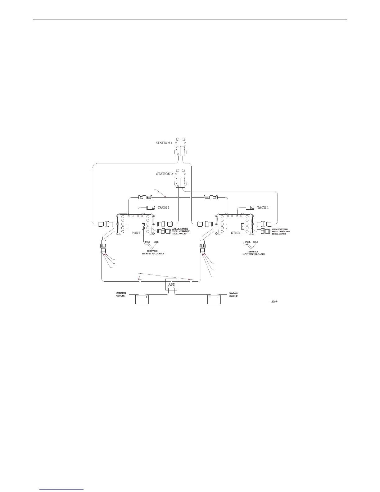
10.1.1.1 9120 (Throttle Servo 2, Shift Solenoid) Processor and 9122 (Throttle Servo 2, Shift
Solenoid, Troll Solenoid) Processor
Figure 10-1: 9120 and 9122 Basic Twin Screw, Two Station Diagram
• The 9120 Processor is designed to precisely control speed and direction on vessels
equipped with mechanical Throttle and Solenoid Clutch Selectors.
• The 9122 Processor is designed to precisely control speed, direction, and trolling valve on
vessels equipped with mechanical Throttle, Solenoid Clutch and Trolling Valve Selectors.
IDLEFULL
33C PUSH-PULL CABLE
IDLE
FULL
THROTTLE
STBD
STATION 2
STATION 1
PORT
12296-
SERIAL COMMUNICATION
10 AMP CIRCUIT BREAKERS
(BY OTHERS)
COMMON
GROUND
COMMON
GROUND
+
-
+
-
APS
CLUTCH PRES.
START INTERLOCK
ALARM
START INTERLOCK
CLUTCH PRES.
ALARM
TACH 1 TACH 1
AHEAD/ASTERN
TROLL COMMAND
TROLL ON/OFF
AHEAD/ASTERN
TROLL COMMAND
TROLL ON/OFF
33C PUSH-PULL CABLE
THROTTLE

 Loading...