10.1 A0 - Station Expander Identification
In applications where there is more than one screw, the system must have some way of determining which
Station Expander is where. Every Station Expander must have it’s own identifying unique number that
corresponds to the Processor it is connected to. At no time can two Station Expanders be identified by the
same Station Expander Identification Number.
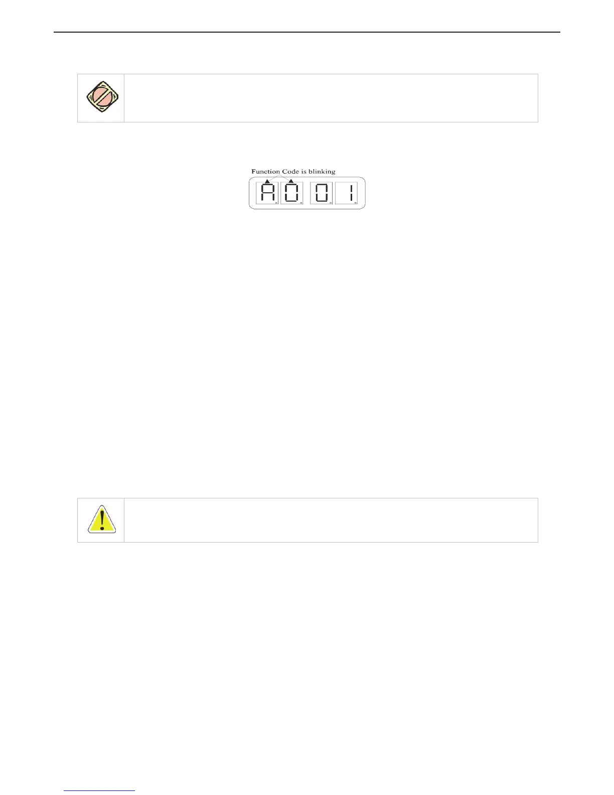
Figure MMC-343-13: Display with A0 - Station Expander Identification Set Up Activated
The values of this Function are 01 (Default Value), 02, 03, 04, and 05.
To change the value:
A Depress any Arrow Push-Button to stop running center dash lines.
B This is the first code on the Function Menu List and the Function Code for Station Expander
Identification.
C Activate Set Up Mode. Refer to section MMC-343: 9: Activating Set Up Mode and Storing a Value.
D Depress either the Up or Down arrows to change the Value of the Function.
E When the value required is displayed, store the value. Refer to section MMC-343: 9: Activating Set
Up Mode and Storing a Value.
10.2 H0 - Diagnostic
This Function is used during Troubleshooting. Refer to the 9000 Series / CruiseCommand Manual supplied
with the Control System for information on this Function.
10.3 H1 - Erase EPROM
This Function is used during Adjustments or Troubleshooting. (For Authorized Personnel Use ONLY)
MMC-343: 11 Dock Trials
Ensure 9000 Series / CruiseCommand System has been installed, adjusted, and tested before performing
the following tests for the Station Expander.
11.1 Control Head (Engines Stopped)
A Turn the power ON to the control system.
B The Control Head at each station will produce an intermittent tone.
C Take command at a remote station.
D Perform each of the following steps on all Control Heads.
CAUTION: This feature MUST be the SAME value as set in the 9000 Series / CruiseCommand Processor the
Expander is connected to.
WARNING: Turn OFF the control system power before disconnecting from the batteries. Do not disconnect
battery terminals when engine is operating.

 Loading...