B Scroll to Function Code E0.
C Activate Set Up Mode.
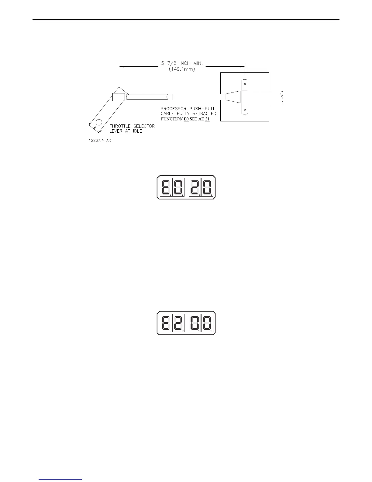
D Scroll Up or Down until the Value 21 is displayed.
Figure 5-22: Example: Throttle Push-Pull Cable Fully Retracted Position for Idle
E Store the Value to memory. (The Throttle Push-Pull cable should drive to the
fully retracted position.)
F Do not
connect the ball joint to the throttle lever at this time.
Figure 5-23: Display LED Function E0 Set Up Activated
5.7.0.1.2 Function Code E2 – Throttle Minimum
This Function further adjusts the Push-Pull cable’s Idle position electronically. The primary
purpose is to adjust the Push-Pull cable/Throttle Selector Lever’s position so that any further
movement will result in an increase in engine RPM. (No Dead-band)
The available Values for this Function are 00.0 to 20.0%.
The Default Value is 00.0%. This value will always be 10% or more below E3 Throttle
Maximum.
To determine and change the Value (Refer to Sections Section 5.2: Activating Set Up Mode
and Section 5.3: Storing Values To Memory):
A Ensure that the Throttle push-pull cable is connected to the Throttle lever.
B Scroll to Function Code E2.
C Activate Set Up Mode.
D Scroll Up until the engine RPM begins to increase above Idle.
E Scroll Down until Idle RPM is reached.
F Store the Value to memory.
Figure 5-24: Display LED Function E2 Set Up Activated

 Loading...