4.4.5 Locations 1 - 9 Installation
4.4.5.1 Seven-Conductor Control Head Cable (Locations 1, 2, 3, 6, and 7)
A Run the seven-conductor cable from the Remote Station to the Processor.
B Support the cables using clamps or straps not more than 18 inches (0,5m) apart if not
contained in a conduit. Verify cable location protects the cable from physical damage.
C Label each seven-conductor cable at both ends with the station it connects, and Port or
Starboard.
D Place on your wrist the anti-static wrist strap provided, attach the strap to ground, and then
remove the cover from the Processor.
E Run the seven-conductor cable for each remote station through the corresponding liquid
tight cable grip on the Processor to the appropriate Station terminal block. Do not tighten
cable grip at this time.
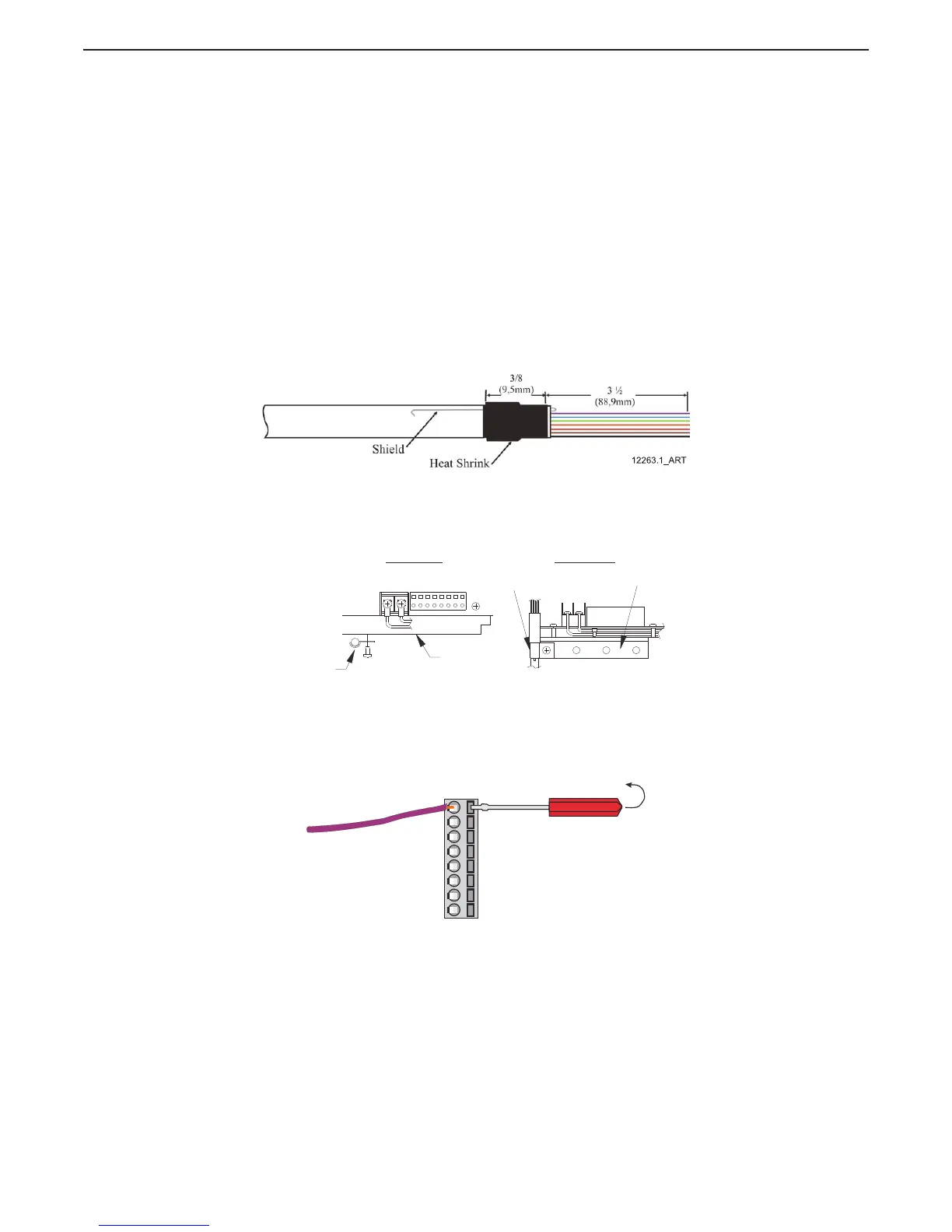
F Strip the PVC jacket and shielding back approximately 4 1/2 inches (114,3mm) on the
seven-conductor cable.
G Strip the wire 3/8 inch (9,5mm) on each lead.
H Pull the Shield wire back against the PVC jacket and slide and shrink a piece of 3/8 inch W.
X 1 inch L. heat-shrink over the cable as shown in Figure 4-12: Seven-Conductor Control
Head Cable Shield Wire and Heat-Shrink
Figure 4-12: Seven-Conductor Control Head Cable Shield Wire and Heat-Shrink
I Secure the seven-conductor cable to the frame using a conductive Clamp. Ensure that the
Clamp and Shield wire come in contact with one another. Refer to Figure 4-13: Clamp
Views.
Figure 4-13: Clamp Views
J Clip the Shield wire so that it is flush with the Clamp.
K Connect the conductors to the appropriate pins as shown on Table 4-2: Processor Circuit
Board Terminal Strip Color Coded Connections for Remote Stations, using a small slotted
screwdriver as shown in Figure 4-14: Terminal Strip Cable Connections
Figure 4-14: Terminal Strip Cable Connections
12266_ART
(CLAMP)
(FRAME)
(CLAMP)
(FRAME)
Top View Side View
12261_ART

 Loading...