L Connect the other station's seven-conductor cables to the appropriate station terminal strips
in the same way.
4.4.5.2 Start Interlock Cable (Location 4)
4.4.5.2.1 Connection at the Starter Solenoid
A Run the length of two-conductor cable between the Engine’s Starter Solenoid
and the Processor.
B Disconnect the Starter Switch wire from the Solenoid.
C Strip back the appropriate amount of PVC jacketing and conductor insulation.
D Connect one of the conductors to the Solenoid’s Starter Switch terminal.
E Butt splice the second wire to Starter Switch wire.
4.4.5.2.2 Connection at the Processor
A Install a liquid tight connector into entry hole (No. 4). (Refer to Figure 4-5:
Standard Enclosure Cable Holes for entry hole location and Figure 4-4: Liquid
Tight Installation for cable grip installation.)
B Run enough of the two-conductor power cable through the liquid tight cable
grip so that it can be routed to PB2 on the Circuit Board as shown in Figure 4-
10: 9221 Enclosure Cable Holes.
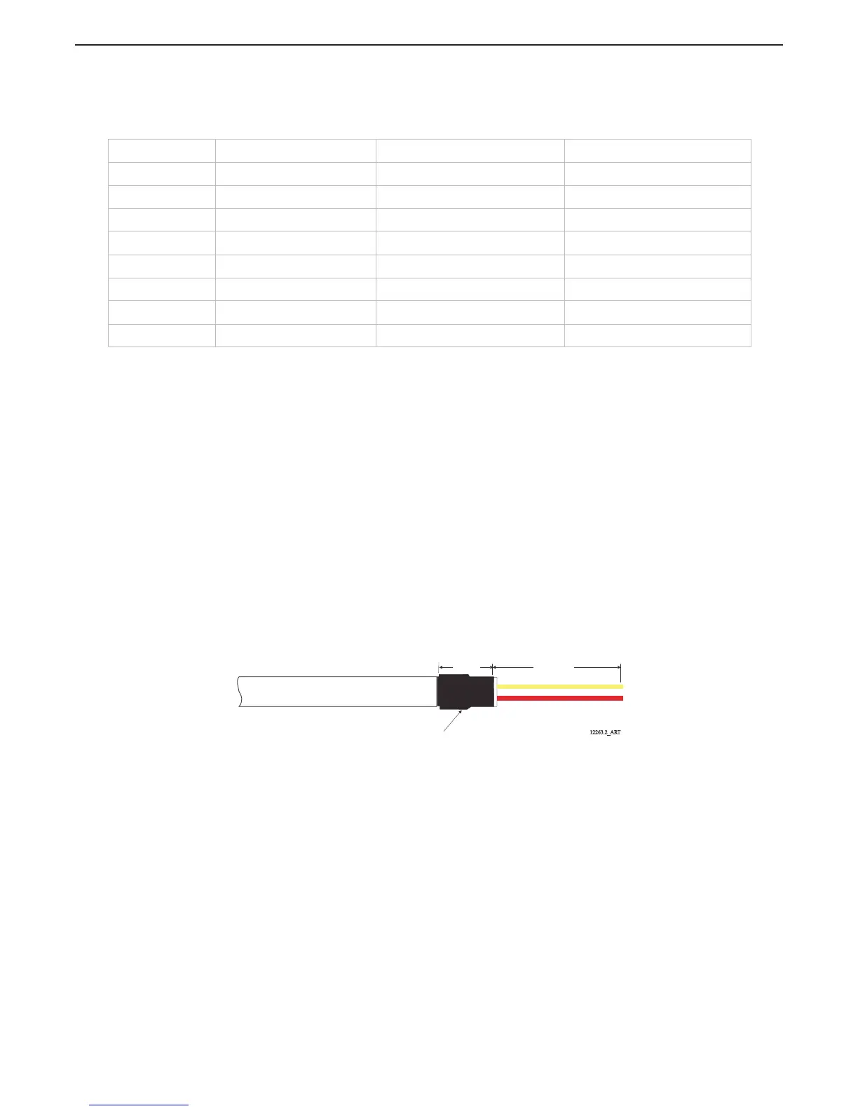
C Strip back 2 inches (50,8mm) of the PVC jacketing. Refer to Figure 4-15: Two-
Conductor Start Interlock Cable
D Strip each wire 3/8-inch (9,5mm).
E Place a 3/8 inch (9,5mm) section of shrink tubing over the cable and heat.
Figure 4-15: Two-Conductor Start Interlock Cable
F Crimp fork or ring terminals to the wires.
G Connect the two-conductor cable to PB2, red lead to the terminal labeled (1)
and yellow lead to the terminal labeled (2), as indicated on Figure 4-5:
Standard Enclosure Cable Holes.
H Tie wrap the start interlock cable to the Processor’s frame.
Table 4-2: Processor Circuit Board Terminal Strip Color Coded Connections for Remote Stations
Conductor Color Processor Termination Left Hand Control Head Right Hand Control Head
Black Station 1 thru 5, Pin 1 Pin 1 Pin 1
Brown Station 1 thru 5, Pin 2 Pin 2 Pin 2
Red Station 1 thru 5, Pin 3 Pin 3 Pin 3
Orange Station 1 thru 5, Pin 4 Pin 4 Pin 4
Green Station 1 thru 5, Pin 6 Pin 6 Pin 6
Blue Station 1 thru 5, Pin 7 Pin 5 Pin 7
Violet Station 1 thru 5, Pin 8 N/C Pin 8
Jumper between Pins 3 and 7. Jumper between Pins 3 and 5.
3/8 inch
(9,5mm)
3 inches
(76,2mm)
Heat Shrink
12263.2_ART

 Loading...