• For Functions E1, E2, E3, E4, E6, and L4 connect the 8-Pin connector of the Service Field Test Unit
into the Processor Throttle connector and to the Throttle Wire Harness.
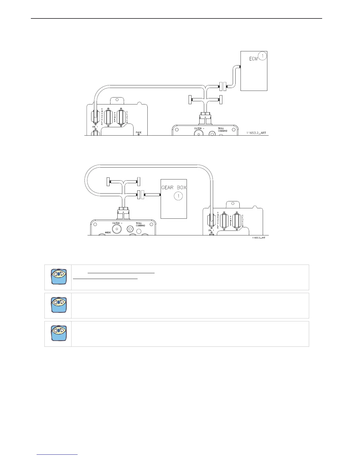
Figure 5-9: E1, E2, E3, E4, E6, L4 Processor, Test Unit, and Multimeter Connections
• For Functions L2, L3, C6, and C7 connect the 12-Pin connector of the Service Field Test Unit to the
Processor Clutch connector and to the Clutch Wire Harness.
Figure 5-10: L2, L3, C6, and C7 Processor, Test Unit, and Multimeter Connections
5.6 System Programming And Adjustments
NOTE: SINGLE SCREW APPLICATIONS: The Function Values may be entered and stored in any order.
TWIN SCREW APPLICATIONS:
The A1 Function must be set FIRST, and the A0 Function must be set SECOND.
The rest of the Function Values may be entered and stored in any order.
NOTE: Power must be turned ON to the Processors when programming or making any adjustments to the
System.
NOTE: In order to prevent nuisance alarms when first setting up a System, some Function Codes take up to 5
minutes to become ACTIVE. The Functions affected by this are the functions that rely on the Serial
Communication, such as A0, A1, A2, A3, E7, and L0. Cycling power Off, then On, expedites these features
making the Functions available immediately.

 Loading...