700 Series Standard Control Head Variations
This Service Sheet reflects all current variations of the standard 3-detent ZF Marine Electronics 700 Series
Control Heads.
1. REQUIREMENTS:
MicroCommander/ClearCommand: one (1) 8-Conductor Cable per Control Head lever.
Pluggable MicroCommander/ClearCommand:
one (1) Control Head Harness per Control Head lever.
CruiseCommand
: one (1) Control Head Harness per Control Head lever.
Included with the Control Head:
• (4) Flat-washer - Stainless Steel, 1/4 inch
• (4) Screw - Stainless Steel, Philip Pan Head, 1/4 inch-20 x 1-3/4 inch
• (4) Nut - Stainless Steel, 1/4 inch-20
• (14) Terminal - Flanged For, #6
• (2) Liquid Tight Connector (in addition to those installed at the factory)
When the Control Head is properly mounted on a console, the Control Head is watertight.
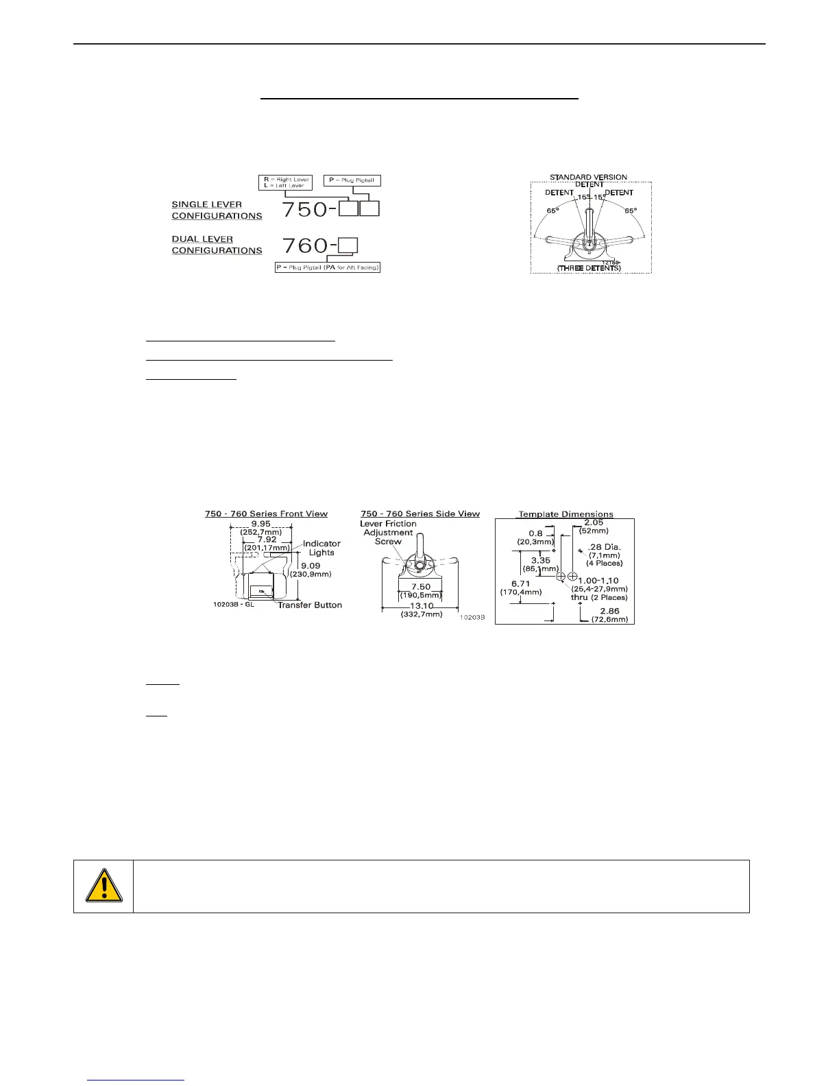
Figure MMC-307-3: Dimensions
2. MOUNTING AND INSTALLATION:
Select the desired mounting locations and drill screw and cable holes as indicated on the template diagram.
Refer to the Dimensions Diagram on the next page.
Run
cable/harnesses between Processor and Control Head. Label both ends with the Station ID. (EXAMPLE:
Port, Center, or Starboard; Port Thrust, Port Throttle; etc.)
There are two types of Control Head connections available: Plug or Terminal Connected. Both types may be
used with MicroCommander, ClearCommand, or CruiseCommand using the appropriate cable or harness.
Follow the appropriate steps for the Control Head that has been supplied for your system.
Figure MMC-307-1: Part Numbering Configurations
Figure MMC-307-2: Detents Available

 Loading...