4 Installation
4.1 Processor
A Secure the Processor to the mounting surface with three 1/4 inch or M6 fasteners, leaving the fourth
fastener unused at this time.
B Connect the Processor to the Hull or Bonding Bus by running a 12 AWG or larger wire between the
Processor’s fourth mounting fastener and the Bonding Bus. (The Processor is bonded if mounted
directly to a metallic surface that is connected to a metal hull) (Refer to MMC-287 Grounding
(Bonding))
4.2 Control Head(s)
4.2.1 400, MC2000 and 700 Series Control Heads
Refer to the appropriate Control Head Dimensions and Variations Service Sheet in Section 11:
Appendix A - System Components and Specifications for installation.
4.2.2 500 Series Control Heads
Refer to the Installation Manual supplied with the 500 Series Control Head Assembly for installation
instructions.
4.2.3 Handheld Remote Controls
Refer to the Installation Manual supplied with the Handheld Remote for installation instructions.
4.3 Wire Harness Installation
The standard Off-the-Shelf Processor has five Pigtails with plugs on the ends. Two of the plugs are for
Remote Stations and one each for Power/Start Interlock, Serial Communication, and Tach Sensor. Additional
Harnesses required will depend on the actual installation. Four different styles of plugs are utilized but are
inserted in an identical fashion as follows:
4.3.1 Plug Insertion and Extraction
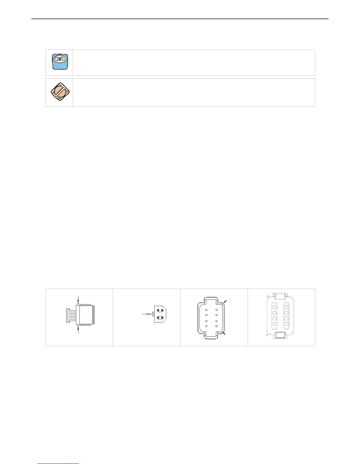
Prior to inserting the plug, pay close attention to the number of pins and the keying of the plug. The plug is
designed to be inserted one way only, but can be forced together in the opposite orientation. Refer to Figure 4-
1: Harness Plug Keying to insert plug correctly.
Figure 4-1: Harness Plug Keying
NOTE: Before starting the actual installation of the Control System, make sure you have the correct parts and
tools on hand. See Section Section 3: Plan the Installation. Read ALL the instructions pertinent to each part
before beginning the installation of the part.
CAUTION: Static electricity can destroy electronic components. Connect the wrist strap provided, to the
Processor frame whenever working on the Processor with the enclosure cover open. This will drain any static
charge you may have on your person.
[
Cable
Depress & Hold
Depress & Hold
11230_ART
Depress
&
Hold
11232_ART
Processor Key
15137_ART
Connector
Keying
Connector
Keying
12
3
4
5 6 7 8
15138_ART

 Loading...