2. Mounting And Installation:
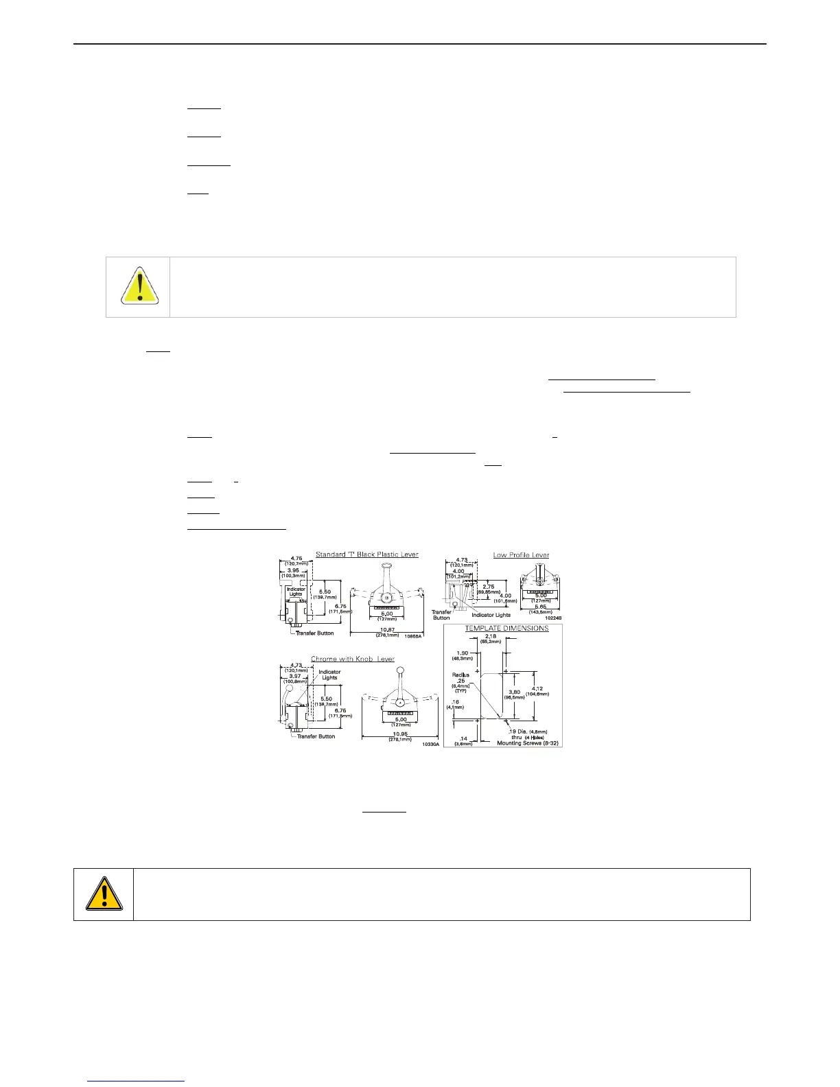
A Select the desired mounting locations and make cutouts per template. Refer to Figure MMC-280-3:
Dimensions.
B Check
that the four mounting screws will start into the Control Head. Remove the Control Head from
the cutout.
C Remove
the backing from the adhesive gasket and apply the gasket adhesive side to the console
around the cutout.
D Run
cable/harnesses between Processor and Control Head. Label both ends with the Station ID.
(EXAMPLE: Port, Center, or Starboard; Port Thrust, Port Throttle; etc.)
There are two types of Control Head connections available: Plug or Terminal Connected. Both types may be
used with MicroCommander, ClearCommand, or CruiseCommand using the appropriate cable or harness.
Follow the appropriate steps for the Control Head that has been supplied for your system.
3. Type 1 - Pluggable
Plug Control Head cable into the pigtail at the Control Head. (Ensure the correct Processor Cable is being
plugged into the corresponding Control Head lever pigtail).
When connecting the plugs, ensure that the release button or buttons are depressed and held
until plug is
fully connected or disconnected. Connecting or disconnecting plugs without depressing and holding the
release button or buttons will damage the plug.
4. Type 2 - Hard-wired
A Strip back the PVC cover on the shielded cable approximately 2-1/2” (63,5mm) at the Control Head.
B At the Control Head end of the cable strip and cut off
the shielding and drain wire flush with the end
of the PVC cover (the drain wire at the Control Head is not
connected to ground).
C Strip
3/8” (9,5mm) insulation off each wire.
D Twist
the individual strands of the wires to minimize fraying.
E Crimp
a locking fork terminal (included with each Control Head) to each of the conductors.
F Make connections
to the Control Head as indicated in the following TERMINAL CONNECTIONS
diagrams.
Figure MMC-280-3: Dimensions
ALWAYS REFER TO THE MANUAL THAT IS SUPPLIED WITH THE CONTROL SYSTEM FOR ANY UNIQUE
CONTROL HEAD CONNECTIONS FOR YOUR SYSTEM.
When cable connections are complete, MOUNT
Control Head to the console using the four (4) mounting
screws and washers supplied with the Control Head.
WARNING: Do not mount control head less than 100mm from Compass.
Mounting control head too close to compass can cause the compass to malfunction.
WARNING: Note that the dimensions are out of scale, pay attention to properly size the cut out before use !

 Loading...