400 Series Control Head Variations
This Service Sheet reflects all current variations of the standard 3-detent ZF 400 Series Control Heads.
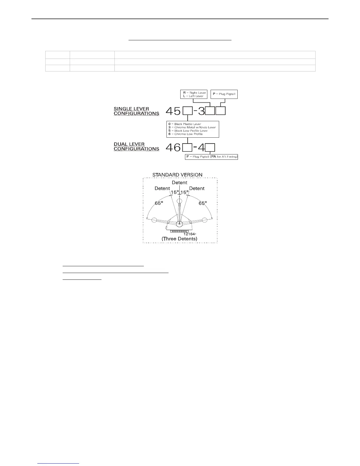
Figure MMC-280-1: Part Numbering Configurations
Figure MMC-280-2: Detents Available
1. Requirements:
MicroCommander/ClearCommand: one (1) 8-Conductor Cable per Control Head lever.
Pluggable MicroCommander/ClearCommand:
one (1) Control Head Harness per Control Head lever.
CruiseCommand
: one (1) Control Head Harness per Control Head lever.
Included with the Control Head:
• Gasket
• Mounting screws and washers
• Terminals (For 8-Conductor or 1-Connector Harnesses)
• Watertight cable grip for the cable entrance on the Processor (For 8-Conductor)
When the Control Head is properly mounted on a console, it is spray proof from the top only. An adhesive
gasket must be used to seal it to the mounting surface. However, below the mounting surface it needs
protection from water or spray. Consider using a Weather Mount Enclosure, which is available from ZF.
Revision List
Rev Date Description
- to N.1 07/10 Previous date unavailable
N.2 02/15/12 Added compass distance note
ZF Marine Propulsion Systems Miramar, LLC
12125 Harbour Reach Dr Ste B
Mukilteo, WA 98275
P - 425-583-1900
F - 425-493-1569
www.zf.com

 Loading...