C Check that the four mounting screws will start into the Control Head.
D Remove the Control Head.
E Strip the adhesive cover from the gasket and apply the adhesive side to the console.
• 700 Series Control Head:
A Use the template supplied inMMC-307 700 Series Standard Control Head Variations and
drill the screw holes and the corner cutout holes.
B Drill the screw holes and the cable holes.
• MC2000 Series Control Head:
A Use the template supplied inMMC-329 MC2000 Series Standard Control Head Variations
and drill the screw holes and the corner cutout holes.
B Saw between the corner cutout holes.
• Check that the two mounting screws will start into the Control Head 500 Series Control Head
Assembly:
Refer to Installation Manual supplied with the 500 Series Control Head Assembly for installation
instructions.
MMC-343: 8 Set Up Procedures
The Station Expander utilizes push buttons in conjunction with Display LED’s to program, adjust, calibrate
and set up the various features. The push buttons also allow you to access and display information
regarding the health of the System.
The following paragraphs explain how to locate and use the push buttons and Display LEDs:
8.1 Station Expander Components Used In Set Up
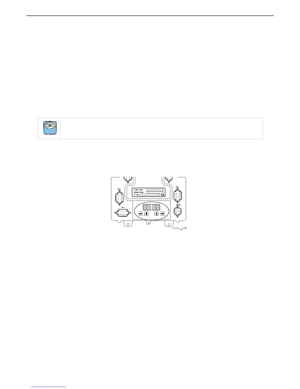
Figure MMC-343-5: Station Expander Display LED and Arrow Push Buttons
Each Station Expander has a Display LED and Arrow Push Buttons located on the front cover. (Figure MMC-
343-5: Station Expander Display LED and Arrow Push Buttons)
• The Display LED is to view the Function Codes and Values. It consists of four 7-segment
display pads.
• The Arrow Push Buttons are used to scroll through and select the Function Codes, and set the
Values.
NOTE: Main Processor function should be set to A3-01 to enable station expander.
11573-1_ART
SERIAL
STA. 4
STA. 2
STA. 3
POWER
PART NUMBER
SERIAL NUMBER

 Loading...