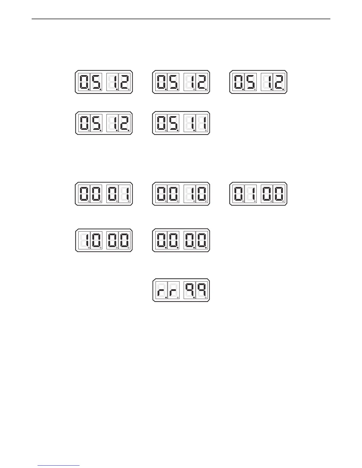
show all five Stations with the lever positioned at the Neutral/Idle position. This will be
covered in further detail later.
F The current status of all the Control Head’s Transfer Buttons can be monitored within the Diagnostic
Menu. A 1 indicates a closure (depressed Transfer Button) of the switch, while a 0 indicates an open
switch. This will also be covered in more detail later.
G Depressing the Up or Down Push Button one more time will show the current revision level of the
software. This feature will provide invaluable information in the years to come. Determining the
characteristics or capabilities of a certain Processor will be as simple as selecting this feature.
Figure 10-13: Example Display Software Revision Level View
H Pressing the Up or Down (Scroll) Push Button once more, returns you to the Applied Battery Voltage.
(Figure 10-9: Example Display of Applied Battery Voltage)
I The Diagnostic Menu can be exited two ways:
• Do not touch any Push Buttons for 5 minutes. The system will automatically exit.
• Depress the Left Push Button until H000 appears. You may now scroll through the Set Up
Menu.
Figure 10-11: Example Display Control Head Lever Current Positions
STATION #1
LEVER A/D COUNT
STATION #4
LEVER A/D COUNT
STATION #2
LEVER A/D COUNT
STATION # 5
LEVER A/D COUNT
STATION #3
LEVER A/D COUNT
Figure 10-12: Example Display Control Head Transfer Button Status View
STATION #1
TRANSFER BUTTON DEPRESSED
STATION #4
T
RANSFER BUTTON DEPRESSED
STATION #2
TRANSFER BUTTON DEPRESSED
STATION # 5
T
RANSFER BUTTON DEPRESSED
STATION #3
TRANSFER BUTTON DEPRESSED

 Loading...