5 Set up Procedure
The Processor utilizes push buttons in conjunction with Display LED’s to program, adjust, calibrate and set
up the various features. The push buttons also allow you to access and display information regarding the
health of the System. The following paragraphs explain how to locate and use the push buttons and
Display LEDs:
5.1 Processor Components Used In Set Up
• Each Processor has a Display LED and Push Buttons.
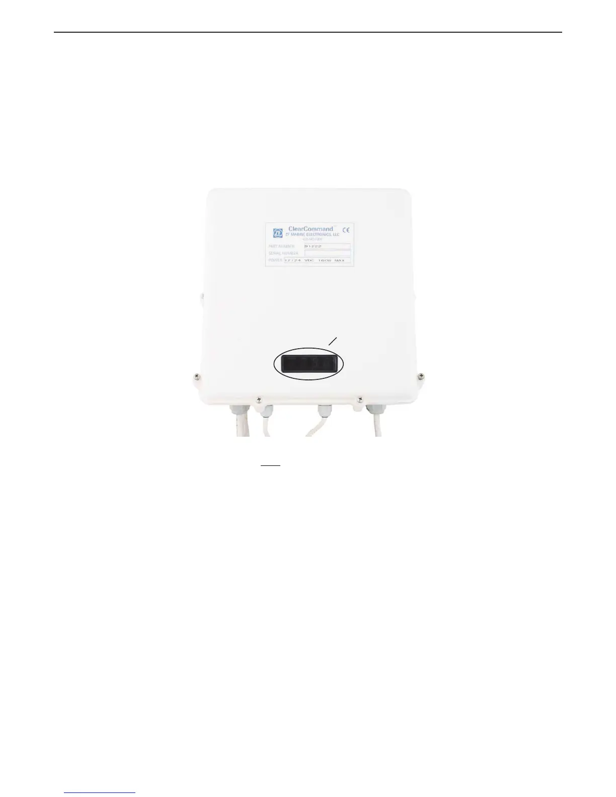
• The Display LED can be viewed through a window on the Processor’s cover as shown in Figure 5-1:
Typical Processor Cover
Figure 5-1: Typical Processor Cover
• The Processor enclosure cover must be removed to access the Push Buttons as shown in Figure 5-2:
Processor Shield Push Button and Display LED Locations
• The Display LED is used to view the Function Codes and the Values for those Functions (Section
5.1.1: Processor Display LED).
LED Display
Window
12268_ART

 Loading...