8 Control Options
8.1 External Alarm Capability
The Processor comes equipped with a normally open relay contact for connection to an external Status
Indication circuit. The relay energizes, closing the contact when the Circuit Board has power applied and the
software program is running normally. In the event of a power loss or the software program detects an
anomaly, the relay de-energizes and the contact opens.
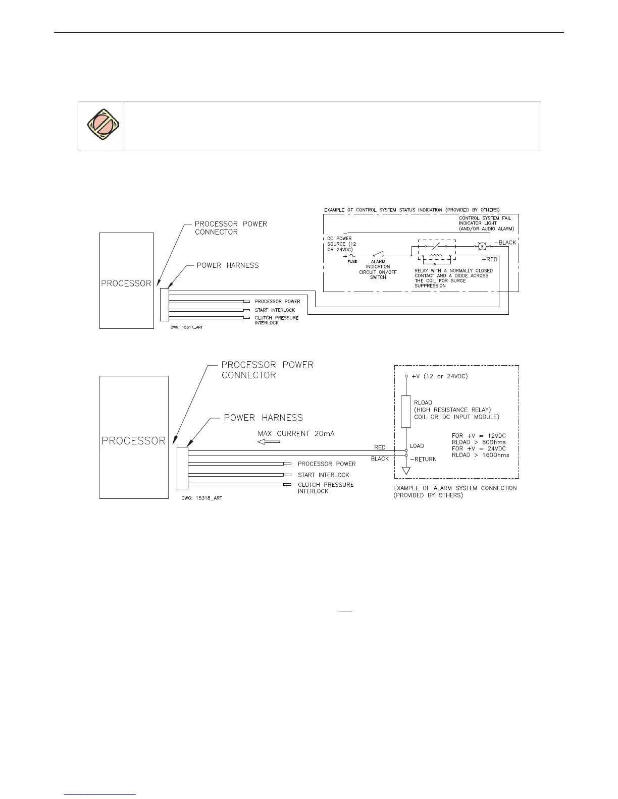
Figure 8-1: External Alarm Connections Processor Hard-Wired Example
Figure 8-2: External Alarm Connections Processor Hard-Wired Example
8.1.1 Installation
(Refer to Figure 8-1: External Alarm Connections Processor Hard-Wired Example or Figure 8-2:
External Alarm Connections Processor Hard-Wired Example)
The following items should be considered when designing and installing the Status Indication Panel:
• The Power Wire Harness (p/n 13631-#) must be used if an External Alarm is required.
• The Processor’s Alarm Circuit uses a “dry” contact. Therefore, the polarity of the conductors is
not a concern.
• The External Status Indication Circuit must not
use the same power source as the Processor.
CAUTION: The Processor’s Alarm circuit is limited to a maximum current of 0.5 Amperes and a maximum
voltage of 100 Volts DC. Exceeding these limits will permanently damage the Alarm circuit.

 Loading...