• The Push Buttons are used to scroll through Function Codes, select Function Codes and set the
Values of the Function Codes. (Section 5.1.2: Push Buttons)
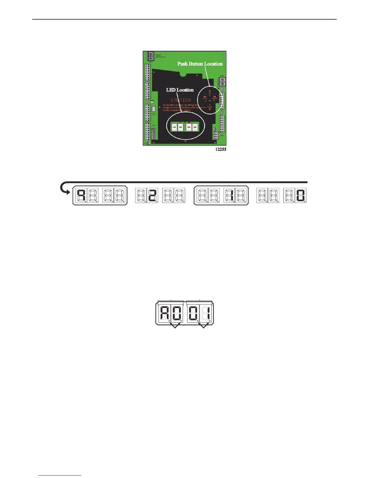
Figure 5-2: Processor Shield Push Button and Display LED Locations
5.1.1 Processor Display LED
Figure 5-3: Display LED at Normal Operation
• The Processor’s Display LED has four 7-segment LED’s, which light up to show either letters or
numbers.
• The Display LED will have the Processor Part Number showing in a running pattern during
Normal operation (Figure 5-3: Display LED at Normal Operation)
• The first two digit Display LED’s to the left, indicate the Function Code, which is
alphanumeric.
• The second two digit Display LED’s indicate the numeric Value that is programmed into the
Processor for the Function Code displayed to the left.
• A decimal point indicator is located on the bottom right corner of each Display LED.
Figure 5-4: Display LED Designations
EXAMPLE: Running Actuator Part Number during Normal Operation (9)
Starts the Processor Part Number again, one number at a time.
12309_ART
Function Code
Value

 Loading...