4.4.6.1.2 Plug Termination
A Strip back 2 1/4 inches (57,15mm) of PVC jacketing.
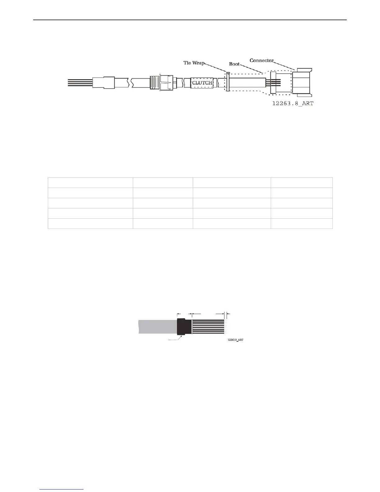
Figure 4-21: Clutch Cable Plug Termination Connections
B Slide the boot onto the cable.
C Strip back 1/4 inch (6,35mm) from the four conductors.
D Crimp Pins onto the eight conductors.
E Insert the pins into the appropriate terminations as shown in Table 4-5: Clutch
Termination Table.
F Slide the boot over the connector.
G Tie-wrap the boot in place.
4.4.6.2 Clutch/Troll Cable (Location 10 & 11)
A single eight-conductor cable must connect the two Shift and two Troll cables to the Processor
through a 12 pin plug.
4.4.6.2.1 Processor Termination
A Install a liquid tight connector into hole no.10.
B Run a 32 inch (0,82m) piece of eight-conductor cable through the liquid tight
connector and tighten, leaving 16 inches (0,41m) outside of the Processor.
C Strip back 4 inches (101,6mm) of the PVC jacket inside the Processor.
D Slide a 1 inch (24,5mm) piece of heat shrink over the end of the cable as
shown in Figure X
Figure 4-22: Clutch/Troll Cable Heat Shrink in Processor
E Strip back 3/8 inch (9,53mm) from the eight conductors and connect to the
Processor as shown in the Table 4-6: Clutch/Troll Termination Table.
Table 4-5: Clutch Termination Table
Description Conductor Color Processor Termination Plug Termination
Ahead Clutch Solenoid (+) Brown TB11-2 Pin 3
Ahead Clutch Solenoid (-) Green TB11-6 Pin 4
Astern Clutch Solenoid (+) Black TB11-1 Pin 5
Astern Clutch Solenoid (-) Yellow TB11-5 Pin 6
12263.9_ART
Heat Shrink
1 inch
(25,4mm)
4 inches
(101,6mm)
3/8 inch
(9,53mm)

 Loading...