G The measurement should be 0 VDC.
H Position the Control Head lever to the Ahead detent. The measurement should now be 12 or
24 VDC, depending on the Solenoid’s rating.
I Position the Control Head lever further forward while monitoring the DC Voltmeter. The
measurement should go from 12 or 24 VDC to 0 VDC at the same time the red LED on the
Control Head becomes lit solid.
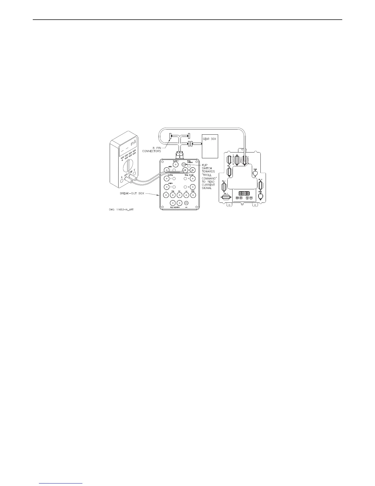
2.3.2 Troll Command
(Proportional Solenoid) Testing with Amp Meter
A Ensure power is removed from both the Processor and the Clutch Power Supply.
B Disconnect the Clutch Harness from the number 3 Processor connector/pigtail.
C Insert the Break-out Box between the number 3 Processor connector/pigtail and the Clutch
Harness as shown in Figure MM13927-13: Troll Connections (Proportional Solenoid).
Figure MM13927-13: Troll Connections (Proportional Solenoid)
D Set up the Multimeter to measure (mA.) and connect the black lead to black socket and the
red lead to the red socket labeled “TROLL COMMAND” as shown in Figure MM13927-13:
Troll Connections (Proportional Solenoid).
E Turn power ‘On’ to the Processor and the Clutch Power Supply and take command at a
Remote Station with the Control Head lever in the Neutral/Idle position.
F Depress the Transfer Button again for approximately 2 seconds until the red LED on the
Control Head begins blinking at a fast rate (Troll Mode Indication).
G Flip switch away from “Troll Command” to read current through meter.
H Move the Control Head lever to the Ahead detent. The current measurement should be the
correct value for minimum clutch pressure (shaft rotations). This value varies depending on
the type of Marine Gear. Refer to the Literature provided with the Trolling Valve and the
Processor for specifics.
I Slowly advance the Control Head lever while monitoring the current. The current should
increase or decrease, depending on the Gear type, in proportion with the Control Head lever
movement. Once again, refer to the Literature provided with the Trolling Valve and the
Processor for specific values.
J Continue to move the Control Head lever forward until the red LED stops blinking (lit steady).
The current should drop to 0 mA.

 Loading...