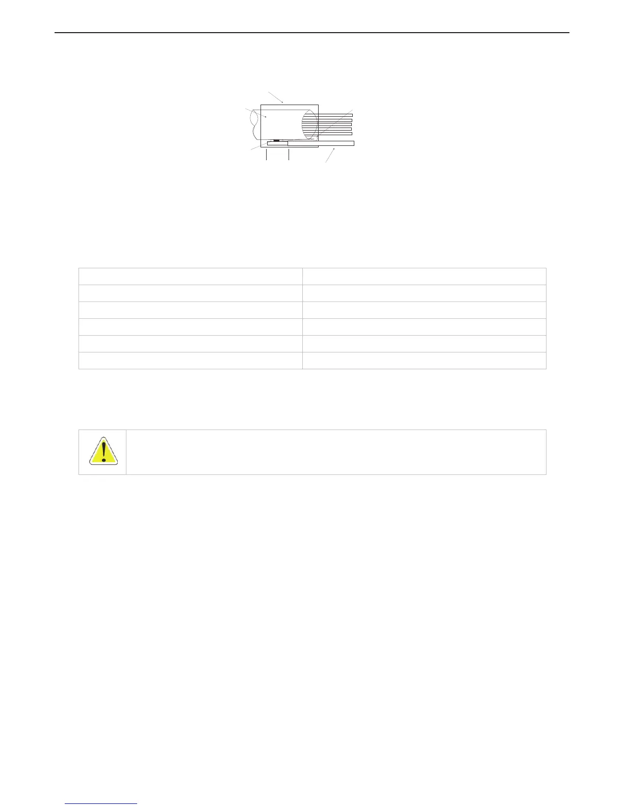
F Pull back the shield wire and solder to a 2 1/2 inch (63,5mm), 18 AWG, green/yellow wire
as shown in Figure 4-26: Engine Shield.
Figure 4-26: Engine Shield
G Slide a 1 inch (25,4mm) section of heat-shrink over the soldered connection and shrink.
H The termination point on TB8 depends on the type of engine to which the Processor is
interfacing. The following table lists the termination points.
4.5 Engine Stop Switches
An engine stop switch(s) must be located at all Remote Stations and capable of stopping the engine at any
RPM. Refer to the installation instruction supplied with the switch and the engine installation instructions for
manufactures recommendations.
Table 4-8: Throttle Termination Table
Throttle Type Termination
DC Voltage (0 to 5.0 VDC) Signal- TB8-5, Return- TB8-7
Current (4.0 to 20.0 mA.) Signal- TB8-4, Return- TB8-7
PWM (0 to 99%) Signal- TB8-3, Return- TB8-7
Frequency ( Signal- TB8-6, Return- TB8-8
Idle Validation (+)- TB8-1, (-)- TB8-2
WARNING: An Engine Stop Switch at each Remote Station is an absolute requirement. Refer to CFR 46, SEC.
62.35-5 and ABYC P-24.5.8.
2.5 inch (63,5mm) of
18 AWG, Green/Yellow Wire
.38
inch
(9,65mm)
Solder Wire
to Shield
Cable
Heat Shrink
.75 inch (19,1mm)
of Cable Shield
12286_ART

 Loading...